4-8 Description and Operation
D-I012.1109EN
innovators in agriculture
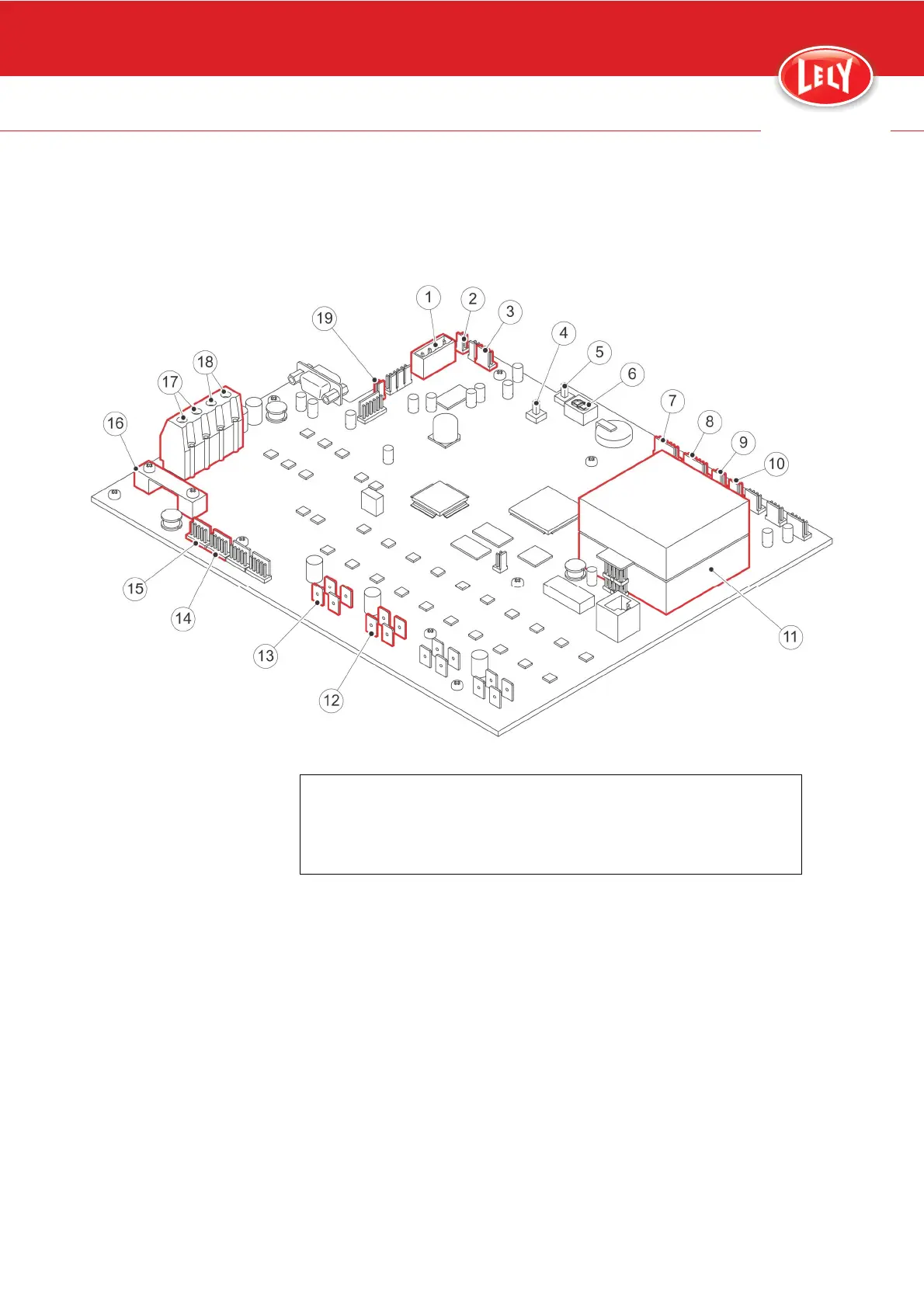
The multiboard pcb sends outputs to the E-Link manual controller,
ultrasonic sensor, motors, encoders and inductive sensors.
The multiboard pcb gets inputs from the E-Link manual controller,
ultrasonic sensor, motors, encoders, inductive sensors.
Figure 16. Multiboard pcb
KEY:
1. E-Link Manual Controller - 2. Interlocking protection ring - 3. Emergency stop button - 4.
ON-button - 5. OFF-button - 6. LED indicator - 7. Ultrasonic sensor right - 8. Ultrasonic
sensor left - 9. Inductive sensor right - 10. Inductive sensor left - 11. Gyroscope - 12. Motor
right - 13. Motor left - 14. Encoder right - 15. Encoder left - 16. Fuse - 17. Loading strips
charger - 18. Battery - 19. Power energizer
Encoders
Each drive motor has an encoder that counts the rotation of the motor
shaft. This information is used to calculate the position of the vehicle.
The encoders send outputs to the multiboard PCB.
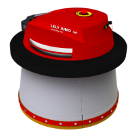
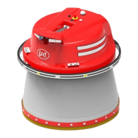
Ultrasonic Sensor
The ultrasonic sensor (1, fig. 17, page 4-9) makes sure the JUNO 150
follows the wall or fence at a pre-determined distance.
A foam ring (3) is attached to on the sensor to minimize reflections and
to focus the ray beam.
The sensor gets inputs from, and sends outputs to the multiboard PCB.