1. Touch the static-protective package that contains the new backplane to any unpainted surface on the
outside of the server. Then, take the new backplane out of the package and place it on a static-
protective surface.
2. Connect the cables to the backplane. See “Server model with four 3.5-inch SAS/SATA drives” on page
30.
To install the backplane, complete the following steps:
Watch the procedure. A video of the installation and removal process is available:
• YouTube:
https://www.youtube.com/playlist?list=PLYV5R7hVcs-DTDY1lmpIPpJVOzo7dKq14
• Youku: http://list.youku.com/albumlist/show/id_52222446.html
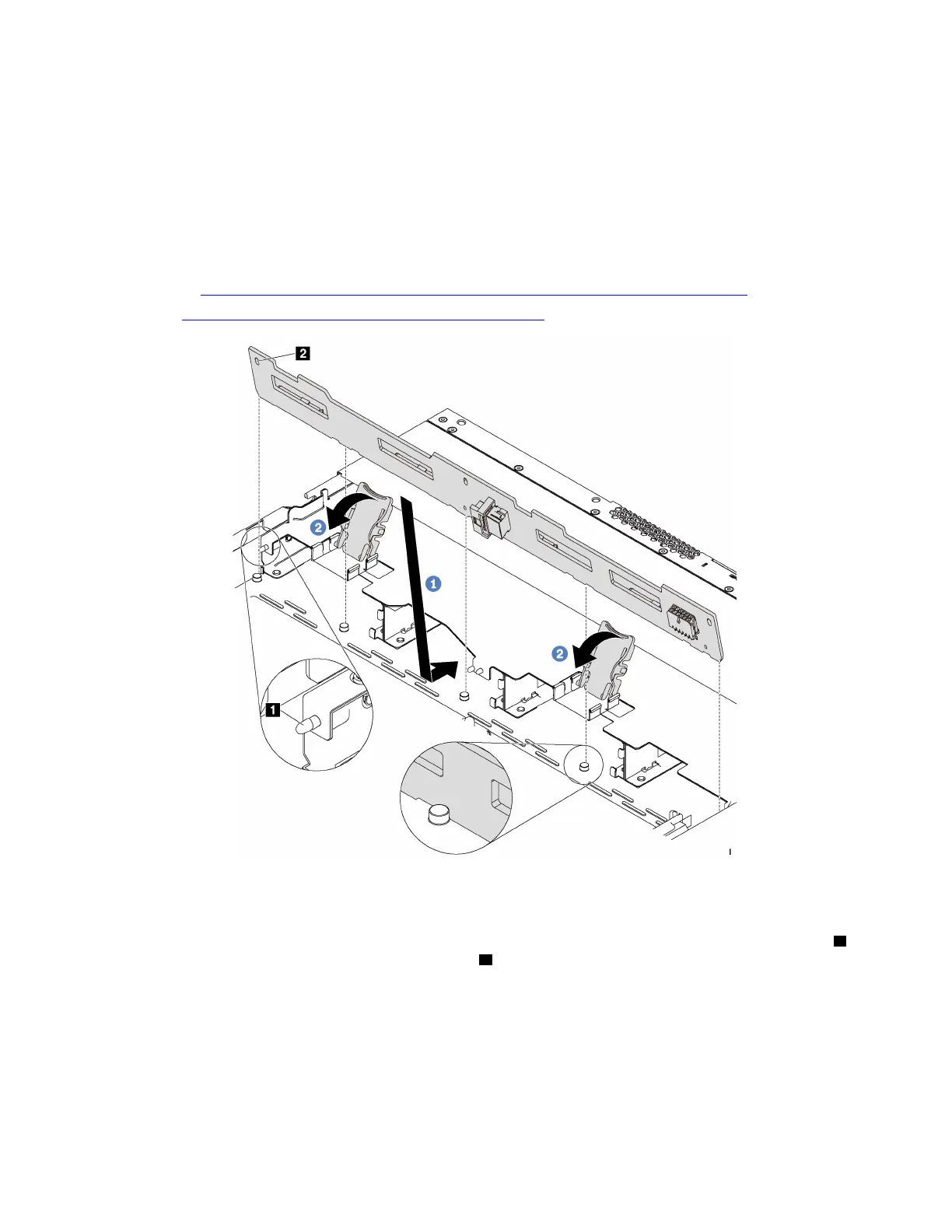
Figure 111. Installation of backplane for four 3.5-inch hot-swap drives
Step 1. Put the backplane under the front I/O assembly cables, align it with the chassis, and lower it into
the chassis. Put the backplane into place with it leaning backward slightly so that the three pins
1
on the chassis pass through the three holes 2 in the backplane.
Step 2. Close the release latches to secure the backplane in place.
After installing the backplane:
1. Reinstall all the drives and drive fillers into the drive bays. See “Install a hot-swap drive” on page 112.
2. Complete the parts replacement. See “Complete the parts replacement” on page 203.
Chapter 3. Hardware replacement procedures 133