Commissioning
Commissioning via DIP switch/potentiometer
6
l
127
EDS84DG752 EN 7.0
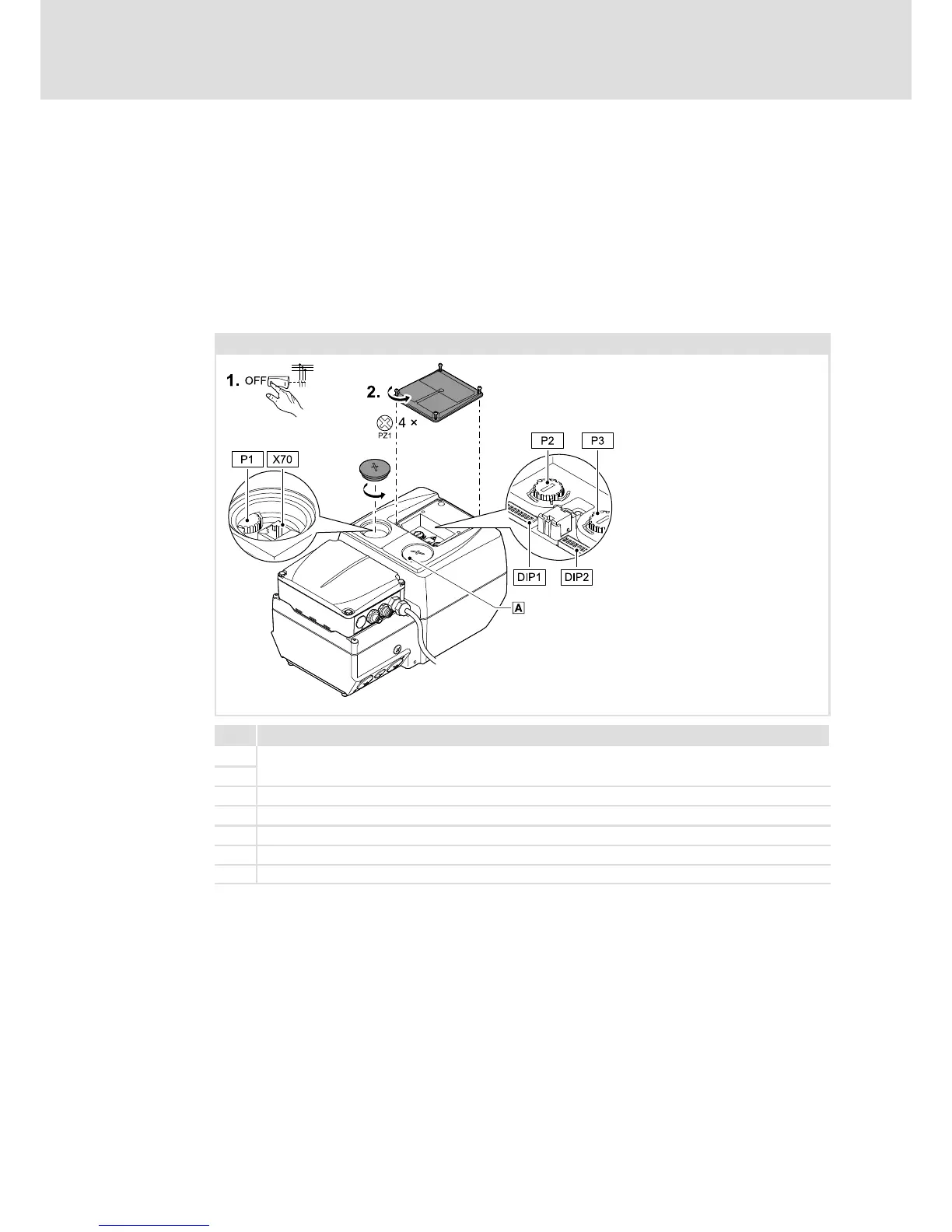
Setting elements 4 ... 7.5 kW
The setting elements are located on the top of the drive unit.
ƒ Provide for isolation from supply and secure to prevent a restart.
ƒ Remove small cover on the top.
Settings carried out via DIP1, DIP2, P2, P3, and P1 must be activated with DIP1/1. The
settings are accepted again at every mains connection. Thus, changes on parameters made
in the meantime may be overwritten.
4 ... 7.5 kW
E84DG083
Name
DIP1
DIP switch for commissioning
DIP2
P1 Setting "Top Cover: Speed ... %"
P2 Setting "Speed ... %", (speed)
P3 Setting "Ramp ... s", (acceleration/deceleration time)
X70 Connection for E94AZCUS USB diagnostic adapter or diagnosis terminal
0
LED status display

 Loading...


