Accessories (overview)
Plug connectors
M12 plug−in connector
9
l
164
EDS84DG752 EN 7.0
9.2 Plug connectors
9.2.1 M12 plug−in connector
The M12 plug−in connector can be easily mounted additionally in the Communication Unit
by breaking out the cutouts. The wiring in the Communication Unit is implemented on
plug−in terminals, thus making it possible to design additional pluggable I/O´s.
Mode Features M12 plug
M12 plug
EZAEVE013/M
l A−coded, 5−pole, female
l Packaging unit: 5 items
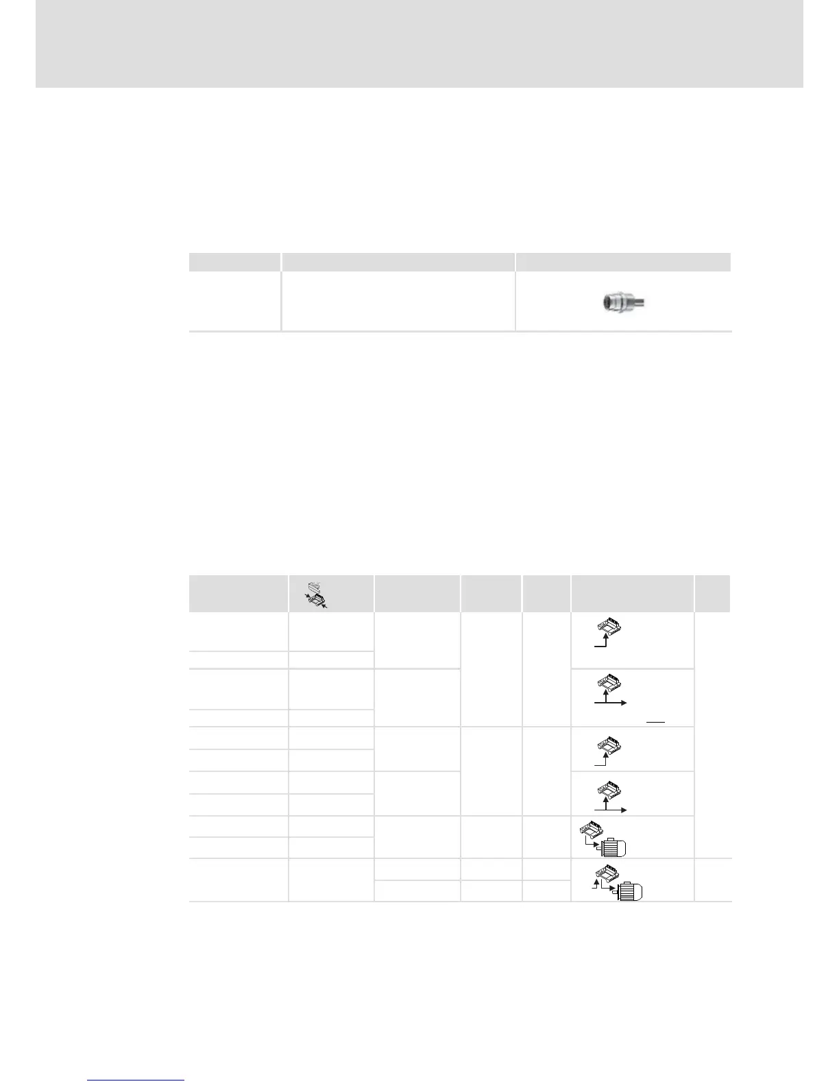
9.2.2 Plug−in modules
By default, cables for the connection of the mains and the motor are led into the WU by
means of cable glands. Alternatively, plug−in modules with prewired Q−plugs can be
supplied for mounting on the right or the left.
For plug−in modules with a Q−plug, an M16 bore for an additional cable gland is available.
Plug−in modules with two Q−plugs are designed for a looping−through connection
(daisy−chain). Like this it is possible to use a supply bus for the machine design.
If wall mounting is implemented, the plug−in modules with a Q8−plug enable the motor
connection as a plug&drive drive, in particular with Lenze system cables.
In the table the retrofittable plug−in modules are listed.
;
.
X...
U
max
I
max
IP
[V] [A]
E84DZEVBLANP ;
X10: Q5
400 ~ 16 ~
~
IP65
E84DZEVBRANP .
E84DZEVBLAFP ;
X10: Q5
X11: Q5
~~
E84DZEVBRAFP . £ E84DGDVB3024...
E84DZEVBLPNP ;
X10: Q4/2
480 ~
24 =
32 ~
10 =
~
=
E84DZEVBRPNP .
E84DZEVBLPRP ;
X10: Q4/2
X11: Q4/2
~
=
~
=
E84DZEVBRPRP .
E84DZEVBLCNP ;
X21: Q8 480 ~ 16
E84DZEVBRCNP .
E84DZEVBLCSP ;
X10: Quickon 480 ~ 20
~
IP65
X21: Q8 480 ~ 16

 Loading...


