2-150 Service Manual
7002-xxx
3
LCD inverter card
Operator panel right cover
assembly
LCD touchscreen display
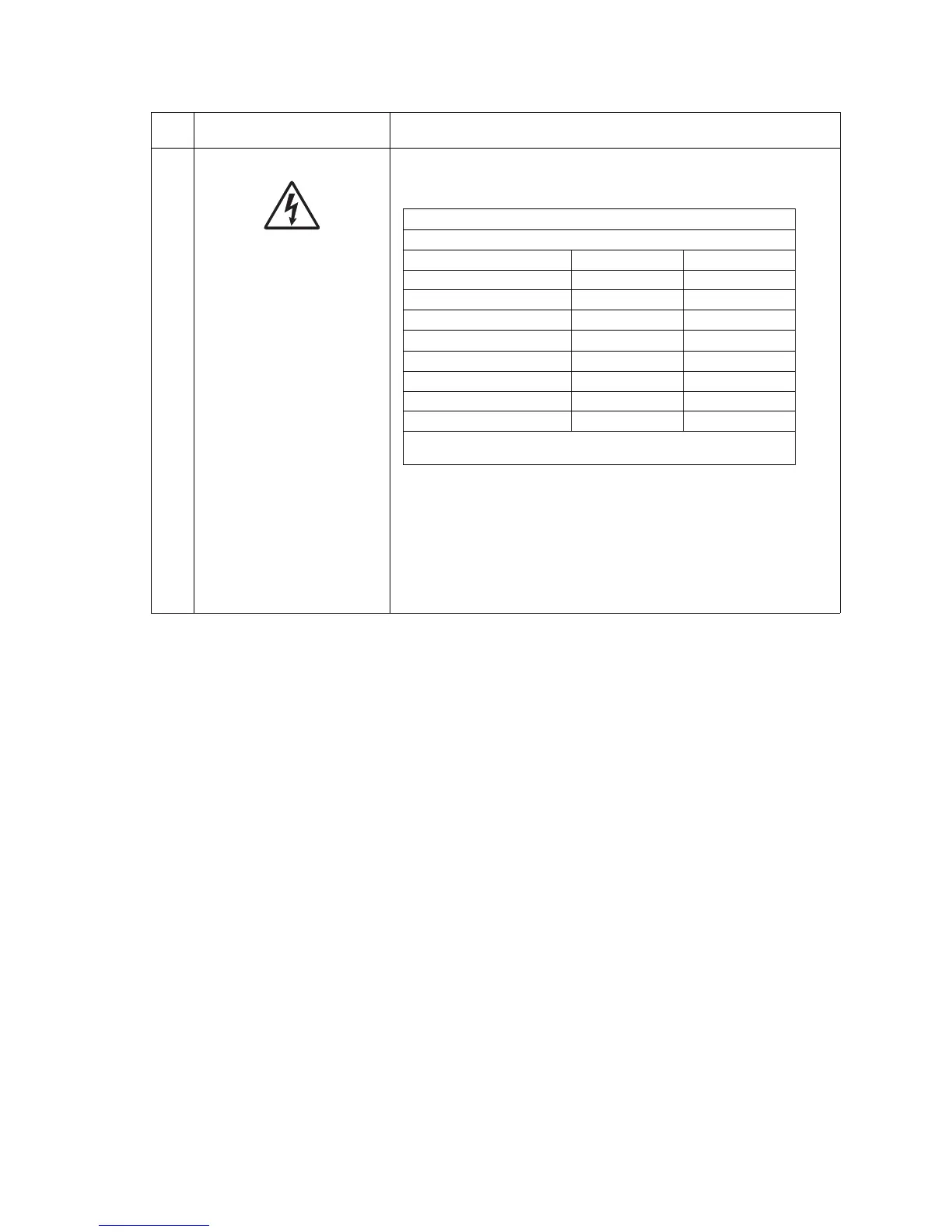
Check the voltages at CN1-1 and CN1-2.
If the voltages at CN1-1 and CN-2 are incorrect, replace the LCD
inverter card. See “LCD inverter card assembly removal” on
page 4-108.
If this does not fix the problem, replace the operator panel right side
cover assembly. See “Operator panel right cover assembly
removal” on page 4-64. If the voltages at CN1-1 and CN1-2 are
correct, replace the inverter card. If this does not fix the problem
replace the touchscreen display. See “LCD touchscreen removal—
models X644e and X646e” on page 4-67.
FRU Action
LCD Touchscreen display
Connector CN1 (LCD inverter card)
Display dark Display lit
CN1–1 Power +12 V dc +12 V dc
CN1–2 Power +12 V dc +12 V dc
CN1–3 Ground 0 V dc 0 V dc
CN1–4 Ground 0 V dc 0 V dc
CN1–5 Lamp Off 0 V dc +4 V dc
CN1–6 Vbright adj 0 V dc +4 V dc*
CN1–7 Ground 0 V dc 0 V dc
CN1–8 Ground 0 V dc 0 V dc
Note: All voltages are approximate values.
*approximate, depending on brightness.