LNC-Lathe New T6-Series
CNC Operation
76 LNC Technology Co., Ltd.
1.7 GRAPH
1.7.1 Function Introduction
Pressing 【GRAPH】 to enter into this function group. The present working path and that of the preview
programs will occur in【GRAPH】screen. Users are able to set the view angle and the display range of the path
display in【SET】screen.
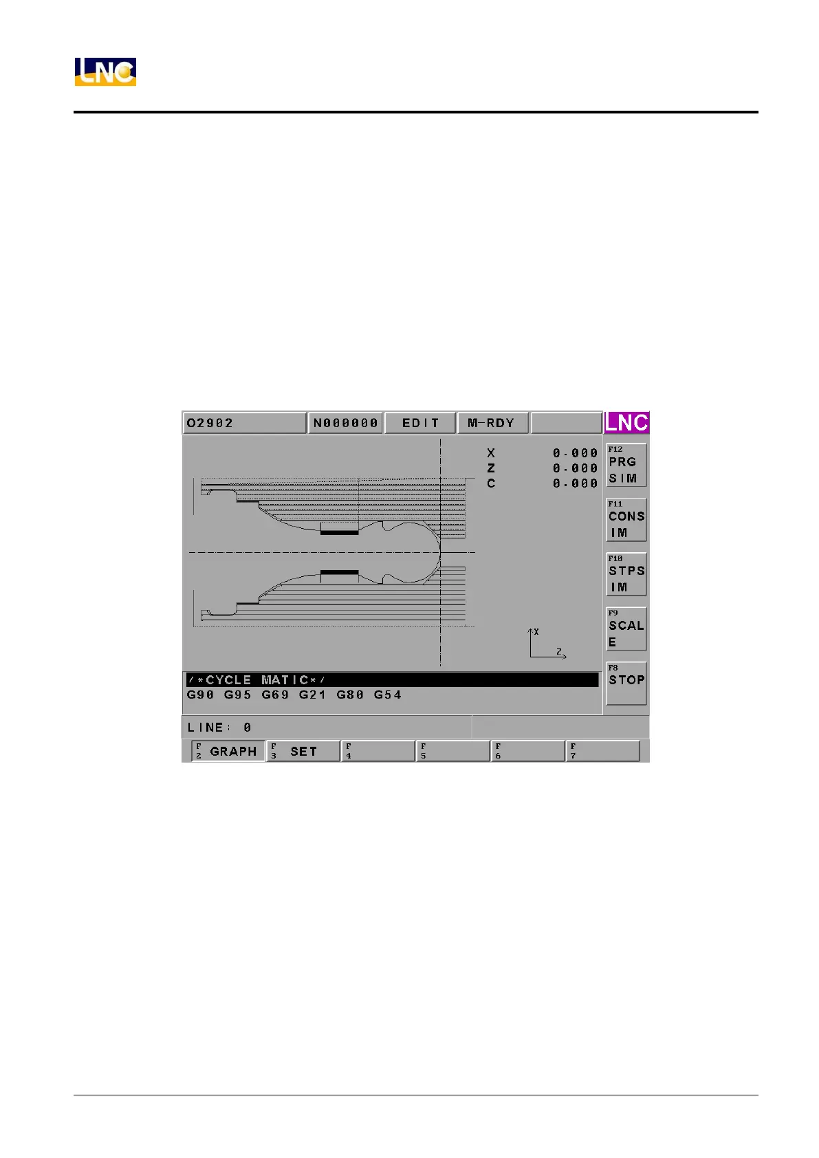
1.7.2 GRAPH
The path display screen is as the below Figure. Coordinate value that is displayed at the upper-right side is the
absolute coordinate of the present tool position. Lower-right side displays the coordinate view angle.
Figure 1.7-1 GRAPH page
【SIMU】:when program is ok, press this button to draw program’s working path.
【CONTINUE】:press this button to re-draw the working program.
【STEP】:Press this button to show step by step of working program.
【SCALE】:Press this button to show 1 square, and under this square this graph will be enlarged. Users can use
<PAGE↑><PAGE↓> to adjust the range. And use< ↑↓> to move this square. When you move to
place you want to see, press <INPUT> or【SCALE】to update the screen to be the square.
【STOP】:when processing【SIMU】或【CONTINUE】, press this button to stop processing.
Note 1: Cursor is green color, G00 is red color and G01, G02 and G03 are yellow color.
Note 2: Cursor is green color, G00 is blue color, and G01, G02, and G03 are pink color. Center line is
bright-green color.
 Loading...