LNC-Lathe New T6-Series
CNC Operation
46 LNC Technology Co., Ltd.
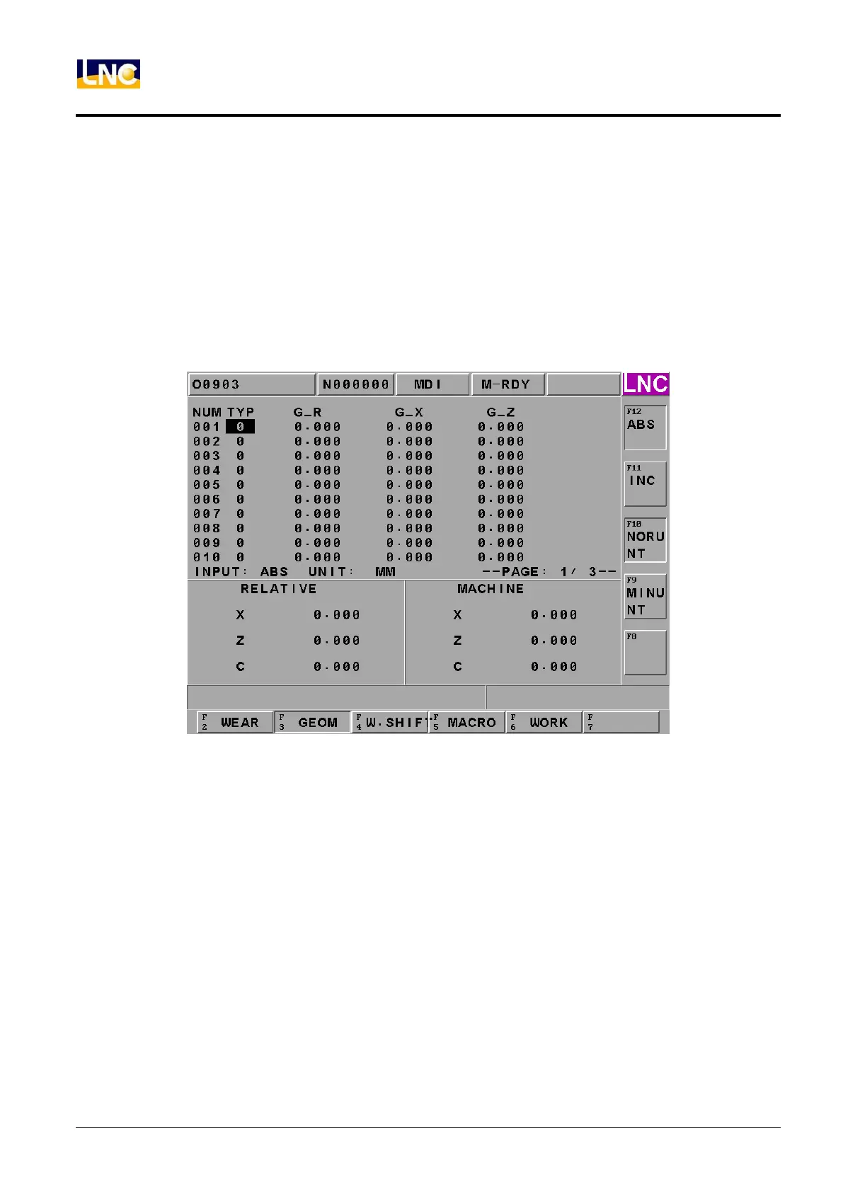
1.5.2 GEOM (Geometry OFFSET)
Pressing 【GEOM】 button to enter into the below screen so users are able to modify under MDI mode.
1. GEOM Outline offset offers 30 types of setting, use <PAGE↓>、<PAGE↑> to change setting screen. Move
the cursor to the one that you want to change, input data into this line, press <INPUT> to write into controller.
2. Everytime when using a tool offset number in a part program, the coordinate will change according to
absolute coordinate. The data will be:
Offset=Machine Coordinate–WORK SHIFT–G54 ~ G59 Offset–Input data
Figure 1.5-4 Tool Outline Offset Screen
【ABS】Input by absolute value, ex: value 0.500, input-0.1, and it will show -0.100.
【INC】Input by increase value, ex: value 0.500, input-0.1, and it will show 0.400.
【NORUNT】Input by normal unit,ex: value 0.500, input 1, and it will show 1.000.
【MINUNT】Input by minimum unit,ex: value 0.500, input 1, and it will show 0.001.
Each column as below:
Type:Tool type
Tool Nose Diameter:Diameter Outline Offset
X Axis Tool Length:X Axis Outline Offset
Z Axis Tool Length:Z Axis Outline Offset
Users can input change data under complete prepared MDI mode. But for X axis and Z axis tool length, users
can use ”MXxx” and ”MZzz” to do offset setting.
 Loading...