2 Chapter 1
System Overview
Locate loss events—Monitor backscatter levels to isolate
losses due to bends, crimps, bad splices, etc.
• “Look inside” devices—Use high resolution and sensitivity to
interrogate individual components within a subsystem.
• Track Polarization—Track changes in the state-of-polariza-
tion as light propagates through an optical network.
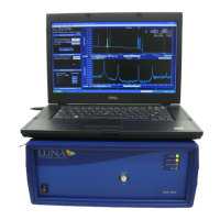
The Control Software
The OBR control software includes an intuitive graphical interface (Figure 1-1). All
controls, options, and
measurement
results are easily accessible from the single main
window or the menu bar. The user selects which parameters are displayed from the
pull-down menu at the top of either plot window.
Caution
Use of controls or adjustments or performance of
procedures other than those specified herein may result
in hazardous radiation exposure and one or more safety
protections may be impaired or rendered ineffective.
The following parameters are calculated and displayed by the OBR control software:
Time Domain Data (Upper or Lower Graph)
• Amplitude (dB/mm) (For a complete definition, see “Time Domain
Amplitude and Amplitude (dB)” on page 180).
• Amplitude (dB) (See page
180).
• Linear Amplitude (See page
181).
• Phase Derivative (See page
182).
• Polarization States (See page 181).
• Magnitude Difference (See page 182)
Frequency Domain Data (Lower
Graph)
• Return Loss (See page
168).
• Linear Amplitude (See page
166).
• Polarization States (See page
166
• Group Delay (See page
169).