4 Chapter 1
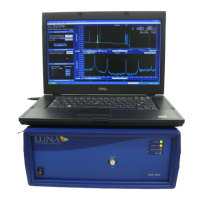
System Overview
The control software also provides many tools for data acquisition, manipulation,
and display. Data may be acquired in standard, spot, or fast scan in continuous or
regular scan mode. Postprocessing allows the user to change the spatial resolution
without the need to redo the measurement. Graph windows support powerful zoom
and cursor
features.
Time Domain Data
By default, the upper graph displays the amplitude of the time domain data, which
is equivalent to a traditional optical time domain reflectometry (OTDR)
measurement. The user may also set the lower graph to display time domain data
by using the pull down graph in the upper right hand corner of that graph.
In the time domain, each optical interface within the device under test produces a
peak. The time domain data can also be displayed in terms of length. This allows
the user to quickly and reliably identify and locate reflections along the length of
an optical system. The phase
derivative
of the time domain data can also be displayed
in the upper plot window. The phase derivative corresponds to the instantaneous
wavelength response of a device. This is particularly useful for devices designed to
operate over narrow wavelength bands like DWDM (dense wavelength division
multiplexed) filters.
The return loss shown in the upper graph gives the single average loss value at each
vertical cursor, for a quick pass/fail evaluation for each optical path or interface.
Frequency Domain
By default, the lower plot shows the linear amplitude of the frequency domain data,
which corresponds to the insertion loss or return loss of the device under test. The
lower plot can also display return loss, polarization states, or group delay.
The frequency domain plot is calculated based on only the time domain data
highlighted by the cursor in the plot window above. Therefore it is possible to
analyze individual sections of a device or system and determine the amplitude and
phase response of each interface separately, by highlighting their corresponding
peaks in the time domain plot. This provides a powerful means for quickly and easily
identifying faults and pinpointing their cause within a component, module, or
subsystem.