Chapter 4
Performing Measurements
Setting Up
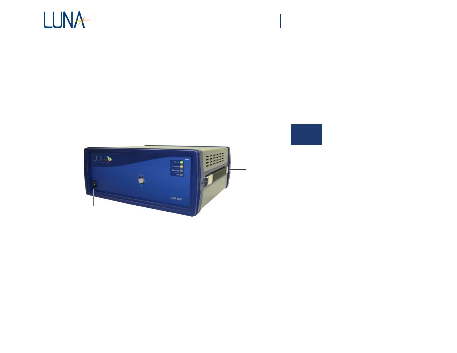
The front panel of the Optical Backscatter Reflectometer contains the power switch
and the optical connector necessary to perform reflection measurements.
4
In
dicator
LEDs
Power switch
Optical Port (FC/APC Connector)
Figure 4-1. The OBR 4600 instrument.
Four LEDs indicate the state of the instrument:
• The Power LED lights when the power is on.
• Laser On lights after the laser has been turned on.
• Scanning lights whenever the laser is scanning.
• USB lights after a scan, while the OBR unit is sending data to the
PC.