68 Chapter 5
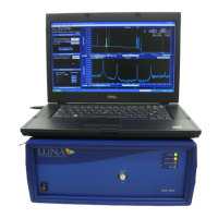
Data Processing and Display
4 If Options > Cursors > Show Integration Area is on (checked), the
regions of the graph around the vertical cursors are highlighted. This
highlighted segment is the only data that will appear in the lower graph.
Lower graphs of all traces will be based on this same segment of the
X-axis.
The user may change the width of the highlighted area (and lower graph X-axis)
by entering a new Integration Width in the Data Processing area of the main
window.
Note: When Options > Sensing Enabled is on or checked (if purchased), the
fields in the Data Processing area change. To control the width of the
highlighted area in Sensing Mode, change the Sensing Range in the Data
Processing area. The menu item for activating these highlighted areas around
the vertical cursors becomes Options > Cursors > Show Sensing Area.
5 Click the blue recalculate button in the upper left of the upper
graph.
By default, the lower graph will be based on the data highlighted around the
left (yellow) cursor from the upper graph, as indicated by the yellow button to
the left of the recalculate button.
6 To see the data from the right (orange) cursor, click to the right of the
recalculate button; the button will turn from gray to orange:
. Then hit the recalculate button again.
Note The recalculate button only appears in the top left
of the upper graph when the vertical cursors are on in the
upper graph
.
7 To change the parameter displayed in the lower graph, follow the next
set of instructions.
Parameter Selection
The user can control the content of the two graphs in the main window from a list
of parameters in the Title Bars. By default, the upper graph displays amplitude (in
dB/mm), but it can also display linear amplitude, polarization states, or amplitude
(dB). The lower graph can also display these same parameters.