174 Chapter 8
Measurement Theory
Both of these interferometer designs can be treated in a basic way using the same
set of mathematics. Consider an input field of the form
E
in
=
E
0
(
t
)
e
–i
ω
(
t
)
t
,
where ω is angular optical frequency, and ω(
t
) describes the instantaneous
frequency of the tunable laser source.
The spatial dependence of the signal may be ignored because the light is detected
only at a single point. At the first coupler, the input field is split into two fields,
E
1
and E
2
. After propagating through different lengths of fiber, the two fields are
recombined, and the resulting field at the detector is
E
ou
t
=
E
0
( t + τ
1
)e
–i
ω
(
t +
τ
1
)
t
+
E
0
( t + τ
2
)e
–i
ω
(
t +
τ
2
)
t
,
where τ
1
and τ
2
are the delays through the two paths of the interferometer.
The electrical output of the detector is proportional to the optical intensity, I, which
is given by the square magnitude of the electric field:
I( ω )
=
E
0
(
t
)
2
+
E
0
( t – τ )
2
+ 2
E
0
(
t
)
E
0
( t – τ )
co
s [ ω(
t
)τ ] ,
8
where the time delay difference between the interferometer paths τ =
Optical Network for OBR
τ
1
– τ
2
.
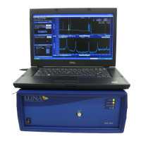
A schematic of Luna’s OBR optical network is shown in Figure 8-2. The optical
system is comprised of a tunable laser source (TLS), an interferometer (the DUT
or device under test), and a detector.