86 Chapter 6
LightPath Analysis Software Guide
(RL) Peak Tolerance (dB) value from -65 to -50. This will allow the peaks in
Features 4 and 8 to
pass.
You may click Apply to see that these peaks are now shown in green, for passing.
Then return to the Parameter Specifications window by selecting Setup > Data
Processing Parameters again.
Change the (IL) Splice Loss Tolerance (dB) value from 0.1 to 0.6. This will allow
the Features 11 and 13 (fibers) to pass. (Splice Loss Tolerance determines both
the maximum and minimum insertion loss values for fiber segments. Min Loss will
now have a value of -0.6, so Features 11 and 13 will no longer have loss values
less than the minimum.)
Click Apply to see that these drops are now shown in green (passing) rather than
red (failing). Features 6 and 10 should now be the only failing features.
Saving LightPath Files
When you first scan or load a trace, the LightPath data files are saved to a temporary
folder. The files can be saved to a permanent folder to be viewed later or to create
6
a reference trace.
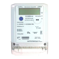
Press the Save LightPath Files button—near the bottom left of the main window—
to save the current trace's data. The Enter Device Descriptor dialog appears
(Figure 6-6), allowing the user to enter a short description of the device. This name
is used to create a subdirectory in the folder that was specified as the Base Folder
for Output Files in the Specify File Paths window (Figure 6-2 on page 80).
Enter the name “golden” to save the data to the folder C:\LPA_Data\golden, and
press OK.
Figure 6-6. Clicking the Save button in the main window calls up
the Device Descriptor window.