214658 24 Revision A
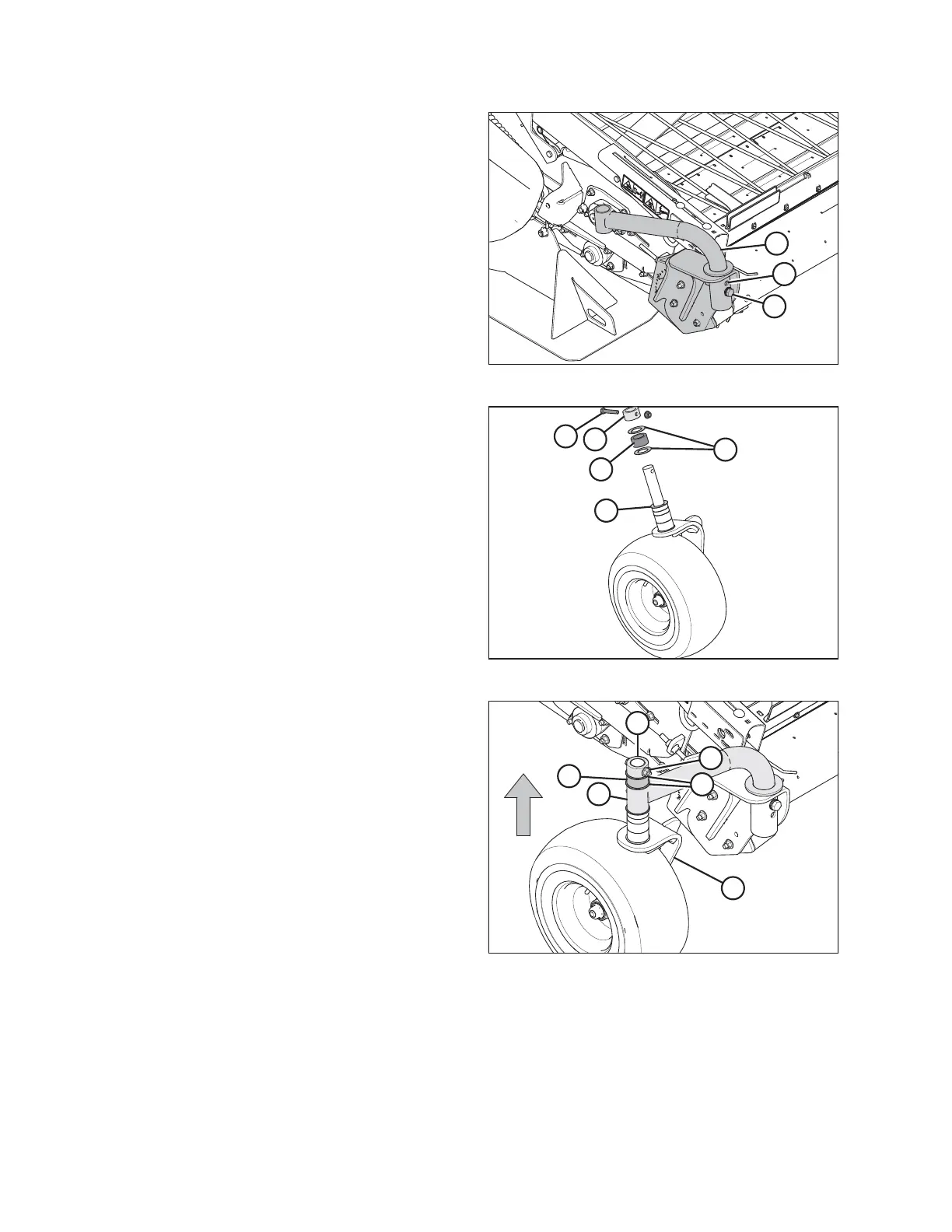
Figure 3.21: Header Wheel Right Side
6. Remove bolt (A) and rotate the caster wheel support
tube (B) until the upper hole (C) is aligned.
7. Install bolt (A) into hole (C). Torque bolt to 234 Nm
(173 lbf·ft).
Figure 3.22: Caster Wheel Assembly
8. Remove the bolt (A), stop collar (E), thrust washers (D),
and spacer (B) from the right caster wheel. Leave thrust
washer (C) on the shaft of the caster assembly.
Figure 3.23: Caster Wheel Assembly
9. Insert the assembly into wheel support tube (E).
10. On the shaft extending past the wheel support tube,
install thrust washer (C), collar (B), thrust washer (D)
and stop collar (F).
11. Rotate the stop collar until the holes line up. Insert
bolt (A), torque it to 68.5 Nm (50.5 lbf·ft).
12. Repeat installation on left side of the header.
UNLOADING THE HEADER