214658 76 Revision A
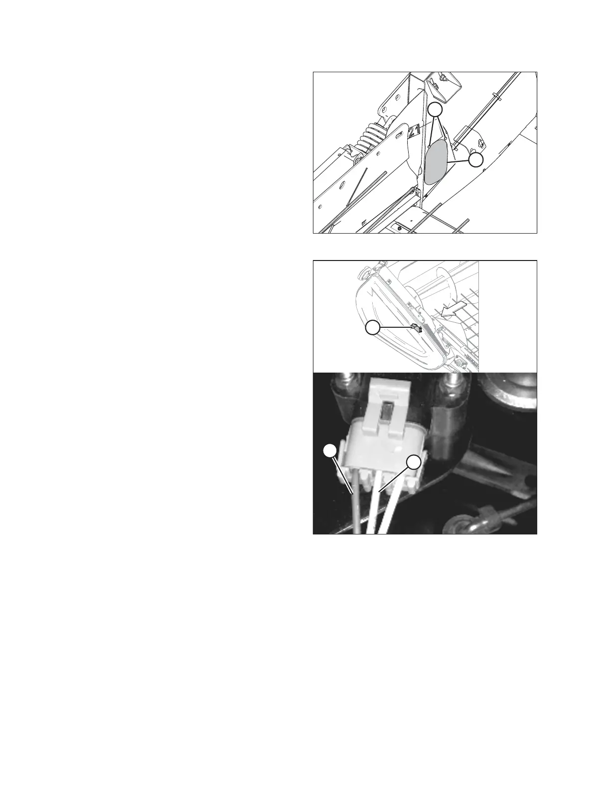
Figure 6.4: Right Access Panel
7. Remove two bolts (A) from access panel (B).
8. Remove access panel (B).
Figure 6.5: Right Height Sensor
9. Locate right height sensor (A).
NOTE:
Sensor may not be exactly as shown, and view of
harness is from inboard side of endsheet.
10. With connector plugged into the sensor, measure
voltage between the orange signal wire (B) in middle
position on connector, and the brown ground wire (C)
on one side of connector. This is maximum voltage for
the right sensor.
11. Start combine and fully lower combine feeder house.
The float springs should be fully compressed. Shut
down combine, and position the key so that power is
supplied to sensors.
12. Repeat voltage measurements for both sensors. These
are the minimum voltages.
13. Compare voltage measurements to specified values. Refer to 6.1.2 Height Sensor Output Voltage Range –
Combine Requirements, page 74.
14. If sensor voltage is outside low and high limits, or if voltage range is less than specified value, adjustments are
required. For instructions, refer to Adjusting Header Height Sensor Voltage Range (Left Side), page 77 or
Adjusting Header Height Sensor Voltage Range (Right Side), page 77.
PREDELIVERY INSPECTION
 Loading...


