214658 78 Revision A
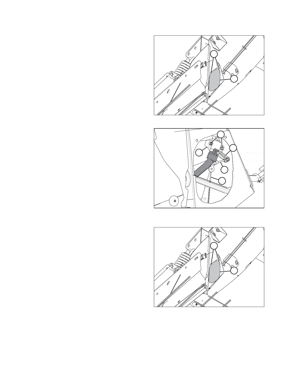
Figure 6.8: Right Access Panel
4. Remove two bolts (A) from access panel (B).
5. Remove access panel (B).
Figure 6.9: Header Height Sensor Assembly –
Right Side
6. Loosen nuts (A).
7. Rotate sensor (B) until desired voltage range is
achieved. Refer to 6.1.2 Height Sensor Output Voltage
Range – Combine Requirements, page 74.
NOTE:
If voltage range is too large or too small, you may need
to relocate linkage rod (C) to a different hole in sensor
control arm (D). If that doesn’t work, relocate linkage
rod (C) to a different hole in sensor control arm (E).
Figure 6.10: Header Height System
8. Once complete, install access panel (B) and secure it
with bolts (A).
NOTE:
Auger removed for illustration purposes.
PREDELIVERY INSPECTION