214658 88 Revision A
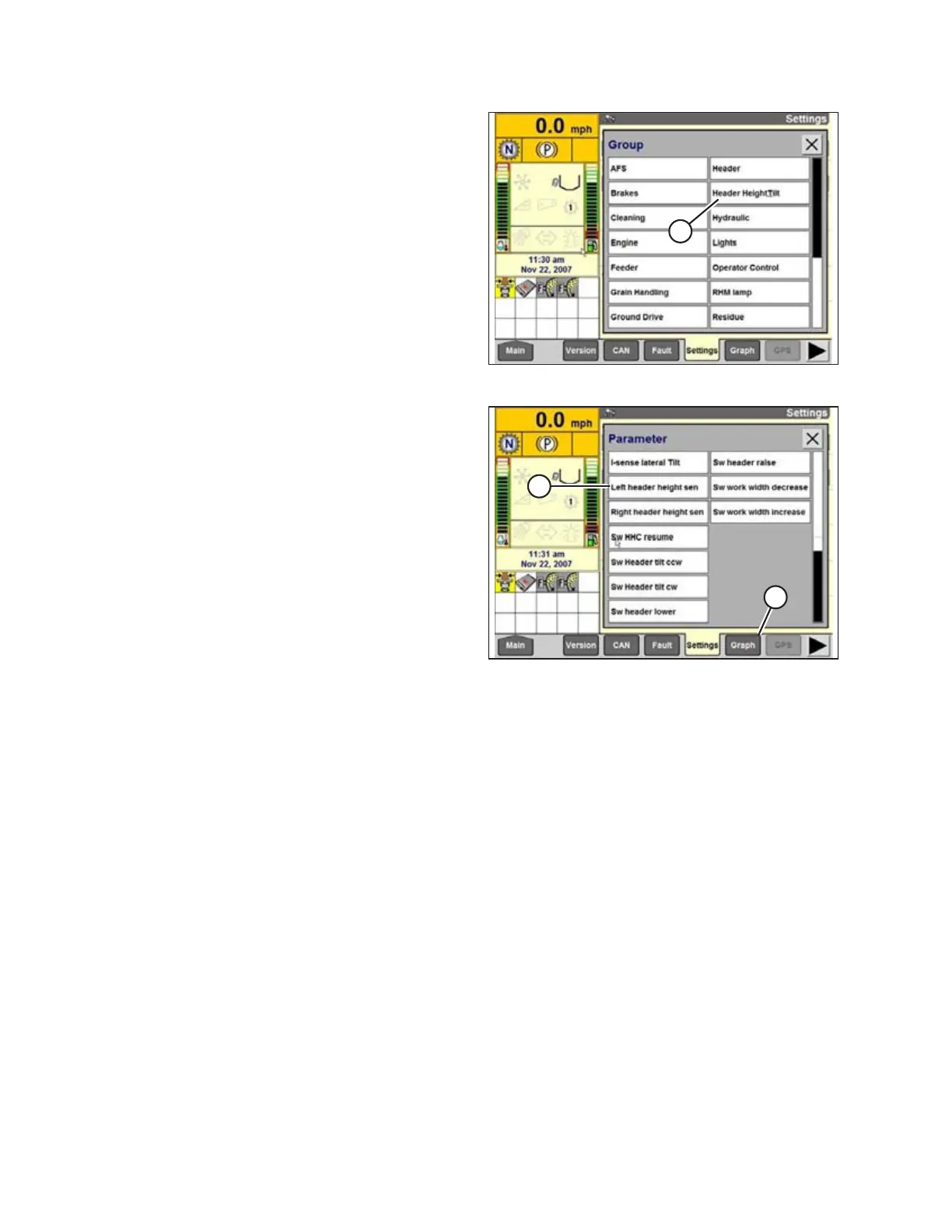
Figure 6.33: Case IH Combine Display
5. Select HEADER HEIGHT/TILT (A). The PARAMETER
page opens.
Figure 6.34: Case IH Combine Display
6. Select LEFT HEADER HEIGHT SEN (A), and then
select GRAPH button (B). The exact voltage is
displayed at top of the page. Raise and lower the
header to see the full range of voltage readings.
7. If the sensor voltage is not within the low and high limits
shown in 6.1.2 Height Sensor Output Voltage Range –
Combine Requirements, page 74, or if the range
between the low and high limits is insufficient, make
adjustments. For instructions, refer to Adjusting Header
Height Sensor Voltage Range (Left Side), page 77 and
Adjusting Header Height Sensor Voltage Range (Right
Side), page 77.
PREDELIVERY INSPECTION
 Loading...


