15
UK
3) Carefully tighten all the screws of the brack-
ets and proceed to fasten the worktable.
Position the wooden worktable (18) and
fasten it with the screws, washers and nuts
as shown in figure 14.
Then insert the following parts in succession:
- front strut (19), 85 mm in width;
- abutting straightedge (20), 60 mm in
height;
- the two straightedges (21), 60 mm in
width, behind the abutting straightedge;
- fasten everything to the worktable with
locking wing-nuts (22).
Fig.14
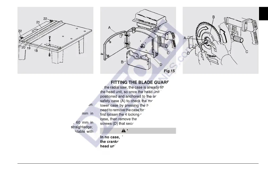
2-7 FITTING THE BLADE GUARD
In the radial saw, the case is already fitted onto
the head unit, so once the head unit has been
positioned and anchored to the arm, open the
safety case (A) to check the movement of the
lower case by pressing the handle (C). If you
need to remove the case for replacing the blade,
first loosen the 4 locking screws from the lower
case, then remove the blade and the 4 locking
screws (D) that secure the case to the flange.
In no case, in normal working conditions,
the crankcase has to be removed from the
head unit.
Fig.15
WARNING
2-8 FITTING OR REPLACING THE
BLADE
Open the blade cover guard, use the handle (C)
to loosen the locking, move the lower guard to
the lower end and stop it in this position. After
locking the guard, there will be enough space
for the blade clamping flange passage (B). To
loosen the nut with left-hand thread (A) in Fig.
16, hold the output shaft introducing a socket
head screw as shown in Fig. 16 and use an
open key clockwise. Mind not to hurt yourself
against the blade while carrying out this opera-
tion. To this purpose, we suggest you wear
gloves. Pull out the external flange (B) so as to
reach the bladeís housing (D). Remove the
blade (D) from the motor inclining and lifting it
after crossing the output shaft. Repeat this
Fig.16
Then insert the following parts in succession:
- abutting straightedge (20), 60 mm in
- the two straightedges (21), 60 mm in
width, behind the abutting straightedge;
- fasten everything to the worktable with
2-7 FITTING THE BLADE GUARD
In the radial saw, the case is already fitted onto
the head unit, so once the head unit has been
positioned and anchored to the arm, open the
safety case (A) to check the movement of the
lower case by pressing the handle (C). If you
need to remove the case for replacing the blade,
first loosen the 4 locking screws from the lower
case, then remove the blade and the 4 locking
screws (D) that secure the case to the flange.
In no case, in normal working conditions,
the crankcase has to be removed from the