19
UK
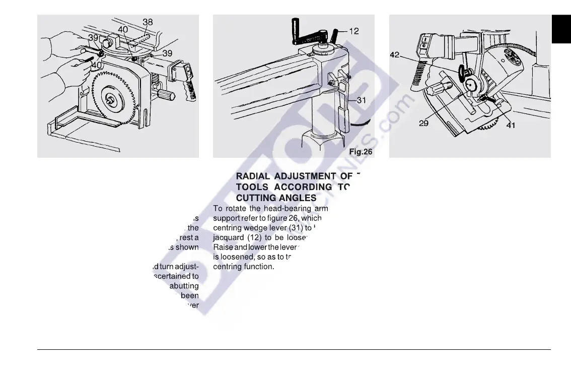
Fig.25 Fig.26 Fig.27
3-3 PARALLELISM OF THE BLADE
WITH REFERENCE TO THE CAR-
RIAGE TRAVEL
If the cut is found to be wider than the blade
thickness and/or the rear side of the cut is
marked, the problem is due to a side slip of the
blade rear teeth. To eliminate this defect, rest a
bracket on the abutting straightedge as shown
in figure 25.
Loosen lever (38) and nuts (39) and turn adjust-
ing screws (40) until the blade is ascertained to
be perfectly perpendicular to the abutting
straightedge. When the operation has been
completed, tighten nuts (39) and secure lever
(38).
3-4 RADIAL ADJUSTMENT OF THE
TOOLS ACCORDING TO THE
CUTTING ANGLES
To rotate the head-bearing arm on the pillar
support refer to figure 26, which shows the self-
centring wedge lever (31) to be raised and the
jacquard (12) to be loosened and tightened.
Raise and lower the lever only when the jacquard
is loosened, so as to take advantage of its self-
centring function.
3-5 TOOL TILT ADJUSTMENT WITH
REFERENCE TO THE WORKTA-
BLE
The machine blade can be tilted to form an
angle of 0° to 45° with the worktable, with the
possibility to automatically lock the blade at
either end. To adjust the blade tilt, act as
described in figure 27.
- Loosen locking handle (41)
- Pull pin (42) to disengage the tool assembly.
- Turn the assembly until the desired tilt angle
is read on indicator (29).
- At the end, always secure locking handle
(41).
thickness and/or the rear side of the cut is
marked, the problem is due to a side slip of the
blade rear teeth. To eliminate this defect, rest a
bracket on the abutting straightedge as shown
Loosen lever (38) and nuts (39) and turn adjust-
ing screws (40) until the blade is ascertained to
be perfectly perpendicular to the abutting
straightedge. When the operation has been
completed, tighten nuts (39) and secure lever
3-4 RADIAL ADJUSTMENT OF THE
To rotate the head-bearing arm on the pillar
support refer to figure 26, which shows the self-
centring wedge lever (31) to be raised and the
jacquard (12) to be loosened and tightened.
Raise and lower the lever only when the jacquard
is loosened, so as to take advantage of its self-