4-35
TMS800E SERVICE MANUAL BOOM
Published 01-29-2014, Control # 496-00
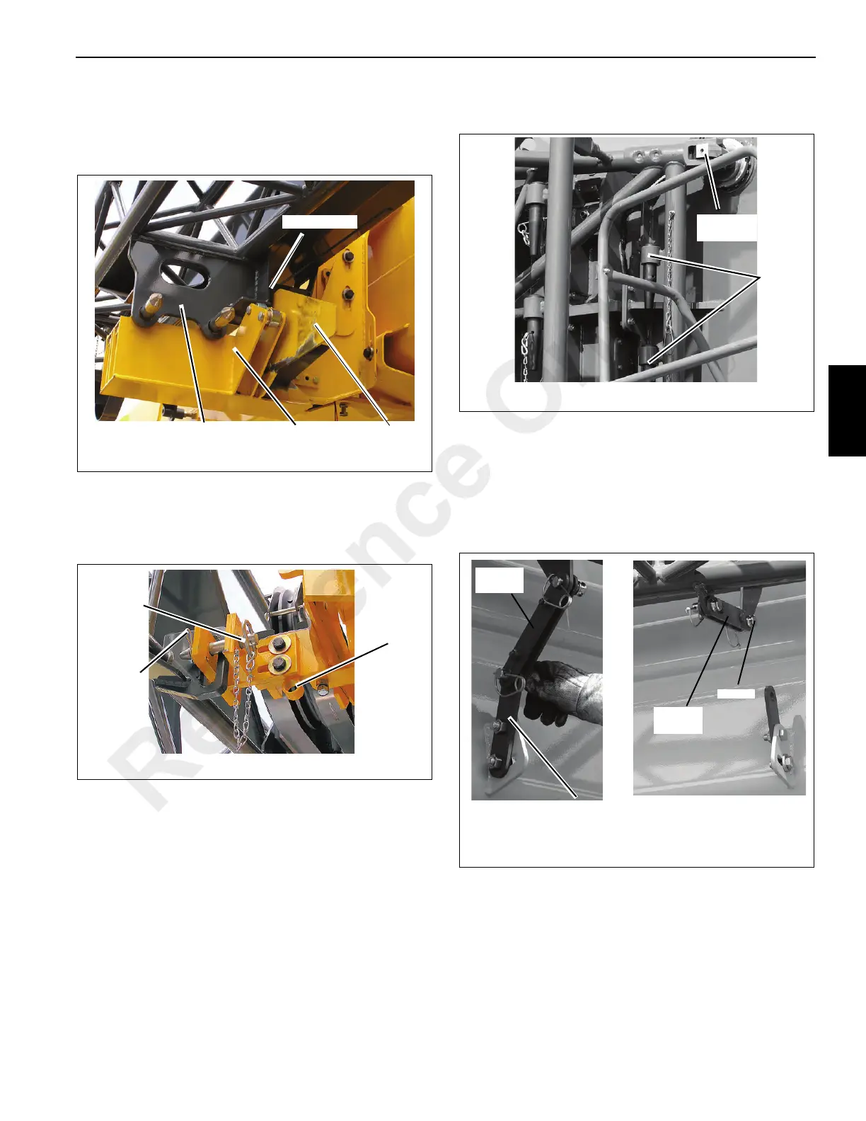
9. Raise the boom to ensure wear pad rests against
bumper plate on ramp (Figure 4-41).
10. Completely retract boom so that the jib stows on the
ramp and front stowage brackets Figure 4-41.
11. Lower the boom.
12. Remove the stowage pin from the holder at the front
mount. Install stowage pin and secure extension to
boom (Figure 4-42).
13. Remove pins from right side of the boom nose. Stow the
pins in pin holders on jib and install retainer clips
Figure 4-43.
a. If the 7 m (23 ft) was left stowed, use controller to
pivot jib in towards boom so that the lugs on 10 m
(33 ft) section align with 7 m (23 ft) section.
b. If using both the 10 m (33 ft) and 7 m (23 ft)
sections, use the controller to pivot jib towards
boom such that the lugs on the 7 m (23 ft) section
align with rear stowage bracket.
NOTE: Perform steps 14 and 15 if stowing the 10 m (33 ft)
section when the 7 m (23 ft) section remained on
the boom, otherwise proceed to step 19.
14. If the bi-fold 7 m (23 ft) section was not used, remove pin
from the base section locking bar. Move locking bar to
the 7 m (23 ft) section and install pin. Secure with
retaining pin Figure 4-44.
15. If the bi-fold 7 m (23 ft) section was not used, remove bi-
fold stowage pin from bi-fold and install at the base
section connection. Install retainer clip Figure 4-45.
6642-47
FIGURE 4-41
Extension Ramp
Wear Pad
Bumper Pad
FIGURE 4-42
Pin
Holder
Stowage
Pin
Clip Pin
6642-46
6642-38
FIGURE 4-43
Upper Pin
Removed
Pin In
Holder
6642-8
Base Section
Locking Bar
FIGURE 4-44
Pin
Locking
Bar
6642-9
Locking
Bar
Reference Only
 Loading...


