4-34
Published 01-29-2014, Control # 496-00
BOOM TMS800E SERVICE MANUAL
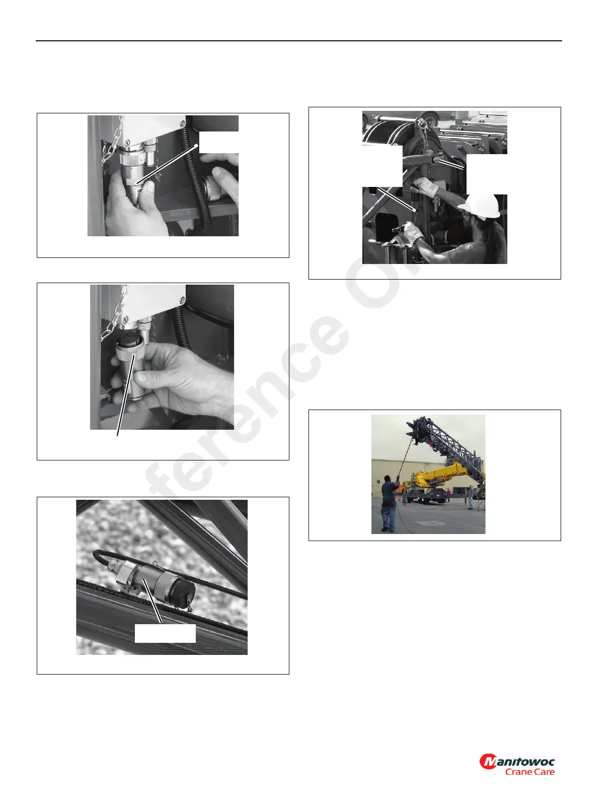
2. Disconnect RCL Cable.
a. Remove connector from junction box on boom nose
Figure 4-36.
b. Install dummy plug on junction box Figure 4-37.
c. Route cable through jib and stow connector
Figure 4-38.
3. Remove retainer clips and remove pins attaching the jib
to the left side of boom nose. Stow the pins in the jib pin
holders and install the retainer clips Figure 4-39.
4. Completely retract boom.
5. Extend boom approximately 61 cm (2 ft).
6. Raise boom above horizontal.
NOTE: Step 7 is stowing with the 7 m (23 ft) section and 10
m (33 ft) section together. If the 7 m (23 ft) section
remained on the boom, proceed to step 9.
7. Use the tag line to maintain control of the jib, and swing
the extension into the stowed position Figure 4-40.
NOTE: Step 8 is with the 7 m (23 ft) section stowed on
boom. If stowing the 7 m (23 ft) section and 10 m
(33 ft) section together, proceed to step 10.
8. Use the tag line to maintain control of the jib Figure 4-40,
and swing the extension into stowed position until tag
line can be attached to superstructure.
6642-21
FIGURE 4-36
Cable End
Connector
6642-20
FIGURE 4-37
Dummy Plug
6642-19
FIGURE 4-38
RCL Cable End
Connector
6642-31
FIGURE 4-39
Remove Pin
From Boom
Nose (Top
and Bottom)
Stow Pin In
Extension
Top and
Bottom)
Reference Only
 Loading...


