8-25
TMS800E SERVICE MANUAL UNDERCARRIAGE
Published 01-29-2014, Control # 496-00
14. Use the correct bushing driver tool to remove the anchor
pin bushings from the spider.
15. Remove the slack adjuster. Reference Slack Adjuster
Removal this Section.
16. Remove the camshaft by grasping the camshaft head
and pulling outboard.
17. Remove the bolts attaching the air chamber bracket to
the spider and pull it away from the spider.
18. Remove spider-to-axle attaching nuts and bolts and
remove the spider.
19. Remove screws and retaining clip securing dust shield
to spider and remove dust shield.
Clean brake parts as outlined below:
1. Wire brush all parts exposed to mud, road dirt, and salt,
to include the spider, air chamber bracket, dust shield,
and exterior of drum.
2. Following the recommendations at the beginning of this
section, use a vacuum cleaner to remove brake dust
from drums. Wipe interior of drums with a greaseless
solvent to remove any spilled oil.
3. Clean all other brake parts thoroughly with a suitable
shop solvent. Wipe dry with a clean, lint-free cloth.
Inspection
1. Check drum for cracks, glazing, grooving, run-out and
out-of-round. Cracked drums must be replaced. Drums
which are glazed, grooved, out-of-round, etc., may be
returned to service if they can be reworked without
exceeding the manufacture’s specifications.
2. Check the spider for expanded anchor pin holes and for
cracks. Replace damaged spiders and anchor pin
bushings.
3. Check the camshaft bracket for broken welds, cracks
and correct alignment. Replace damaged brackets.
4. Check the anchor pins for corrosion and wear. Replace
worn or damaged anchor pins.
5. Inspect the shoes for rust, expanded rivet holes, broken
welds and correct alignment. Replace a shoe with any of
the conditions listed in steps 2 through 5.
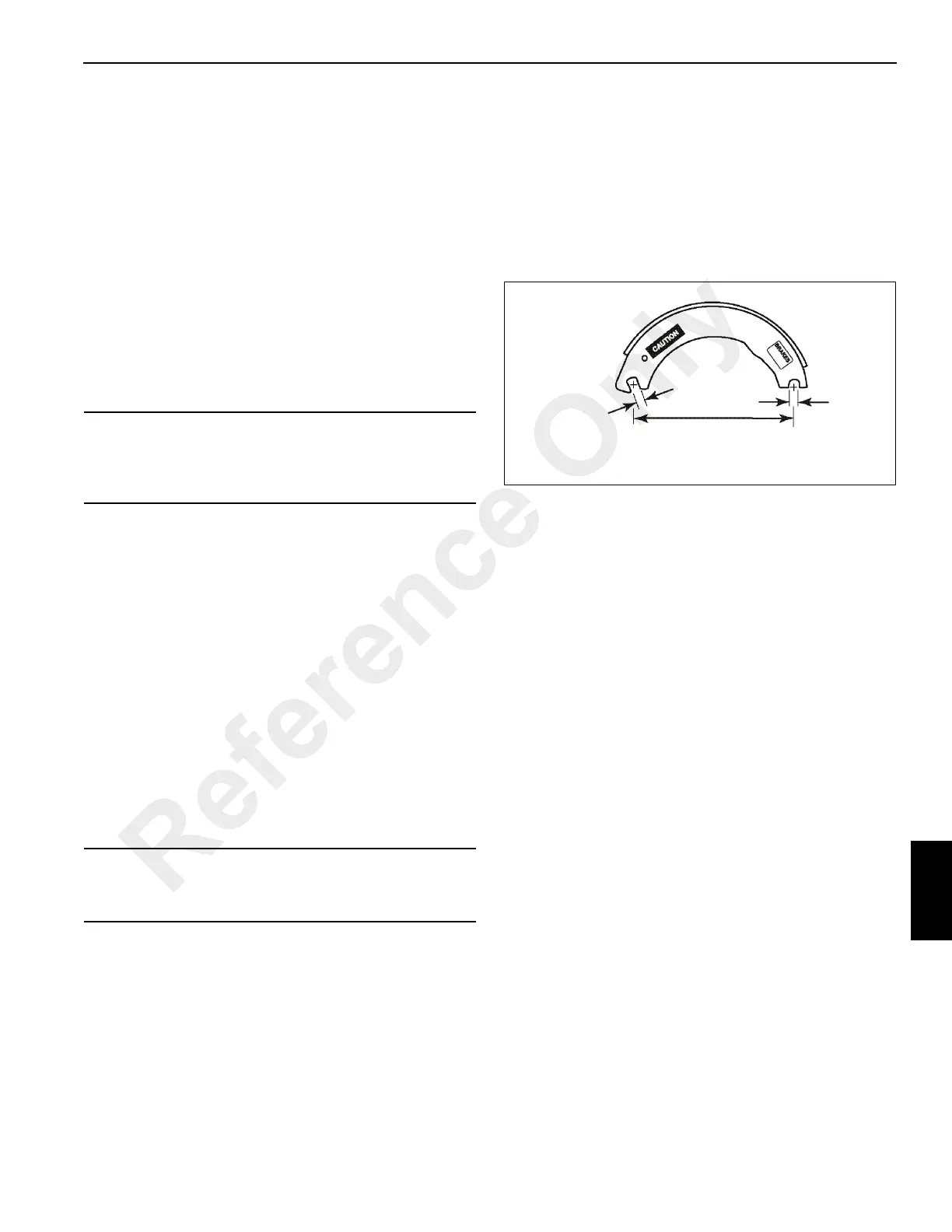
6. Anchor pin holes must not exceed 25.63 mm (1.009 in)
in diameter. The distance from the center of the anchor
pin hole to the center of the roller hole must not exceed
32.46 cm (12.779 in). Replace brake shoes with
measurements that do not meet these specifications
(Figure 8-18).
7. Check the linings and replace the shoes if contaminated,
cracked, or worn to less than 6.35 mm (0.25 in)
thickness at any point.
8. Each time the brake shoes are removed, check
camshaft radial play as outlined below
a. Mount a dial indicator with the plunger on the cam
head at the roller contact area.
b. Zero the dial indicator.
c. Move the cam head up and down and note the
maximum reading.
d. If play exceeds 0.9 mm (0.035 in), rebush the air
chamber bracket. Refer to Repair/Replacement in
this Section.
e. After rebushing, recheck radial play. Replace the
camshaft if play is still excessive.
9. Check the end of the camshaft for cracks and worn or
deformed splines. Replace as necessary.
10. Check the camshaft bushing journals for wear or
corrosion. If the camshaft shows visible wear or if
roughness is felt in the journal, replace the camshaft.
11. Check the camshaft head for brineling, cracking or flat
spots. Replace the camshaft if a ridge can be felt
between the worn areas and surface of the cam head.
NOTE: The camshaft bushings and seals are mounted in
the air chamber bracket assembly.
12. Check the camshaft bushings for deterioration or wear.
The inner surface must be smooth. Replace the bushing
if surface is rough or abrasive.
CAUTION
Oxidation and dirt on the outside of brake drum acts as an
insulator and may hinder heat dissipation. Remove with a
wire brush.
CAUTION
Do not use drum if it exceeds maximum diameter or run-
out specifications.
FIGURE 8-18
Anchor End
Cam End
32.46 cm (12.779 in)
25.63 mm
(1.009 in)
Max.
6597-4
25.63 mm
(1.009 in)
Max.
Reference Only
 Loading...


