8-26
Published 01-29-2014, Control # 496-00
UNDERCARRIAGE TMS800E SERVICE MANUAL
13. Check the grease seals and replace if nicked, cut, or
distorted.
14. Check the air chamber bracket for a bent, broken, or
cracked arm and welds. Replace as necessary.
15. Check the air chamber bracket mounting studs for
looseness, damaged threads, or bent studs. Replace as
necessary.
16. Check the air chamber for leaks, cracked housing, bent
push rod, loose clamp ring, clogged vent holes, or loose
air fittings. Repair or replace as necessary.
17. If the air chamber is replaced or repaired, check the
distance from the clevis pin hole centerline to the air
chamber face. Reference Automatic Slack Adjuster in
this Section for adjustment.
18. If a new air chamber is installed, ensure that the cutoff
push rod does not project too far into the clevis.
Minimum clearance from the clevis centerline to push
rod end is 22.2 mm (0.875 in).
19. Check air chamber clevis pin for cracks and wear.
20. Check the automatic slack adjuster. Reference
automatic Slack Adjuster this Section.
Repair/Replacement
Routinely replace lower cost items such as springs, seals,
bushings, and heavily worn parts. Damage caused by failure
of worn parts is much more expensive than the cost of the
parts.
Camshaft bushing and/or grease seal replacement is as
follows:
1. Remove the air chamber bracket.
2. Drive out the old bushing and grease seal with a suitable
driver.
3. Clean and inspect the air chamber bracket. Reference
Inspection in this subsection.
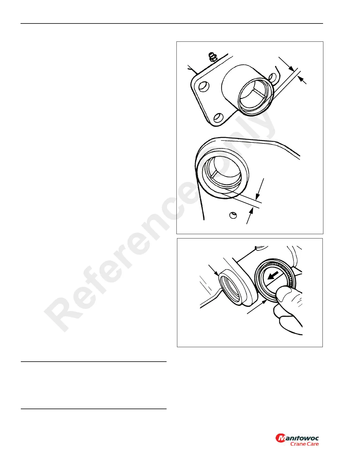
4. Install the new bushings in the air chamber bracket with
a piloted driver. Both bushings are nonmetallic and are
labeled on one end. Install them with the labeled ends
facing each other. The cam head end is recessed 7.1
mm (0.281 in) and the slack adjuster end is recessed
17.5 mm (0.688 in) from the ends of the tube (see
Figure 8-19).
5. Install new grease seals with a piloted driver so the seals
are flush with the end of the air chamber bracket tube
(see Figure 8-20).
CAUTION
Seals must be installed with the lip side (spring side) of
both seals facing toward the slack adjuster end of the
bracket. Improperly oriented seals may allow grease to
exit the camshaft head end of air chamber bracket and
contaminate lining material.
At slack adjuster end,
recess bushing 17.5
mm (0.687 in)
At cam head end, recess
bushing 7.1 mm (0.281 in)
FIGURE 8-19
Install seals flush
with end of tube.
Lip side of both seals
must face toward slack
adjuster end of bracket
FIGURE 8-20
Reference Only
 Loading...


