WRS – Installation Manual
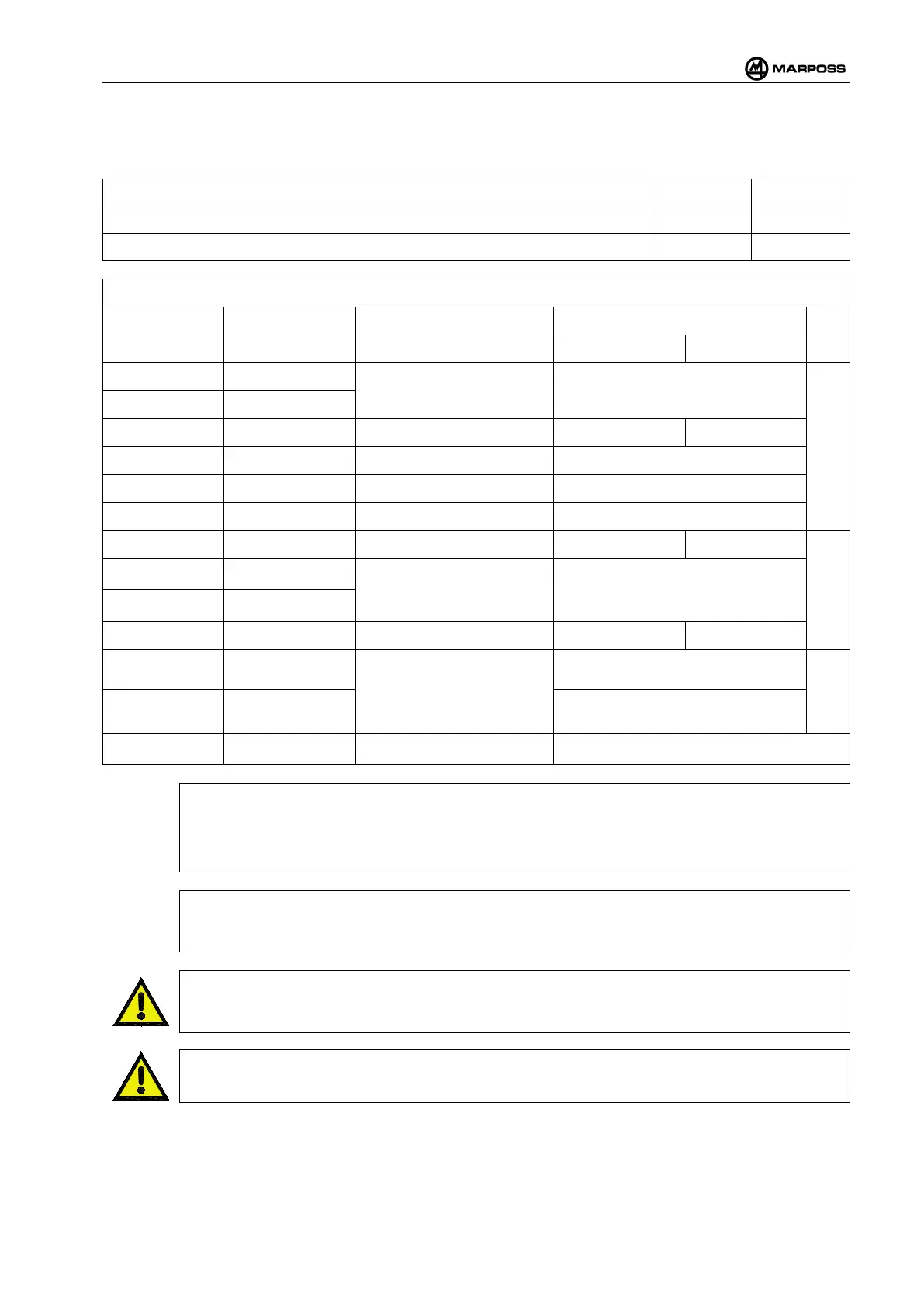
The “+Vdc” symbol in Table 4-9 indicates the highest power supply voltage present (i.e. the + VEXT signal
on the brown lead); the “-Vdc” symbol indicates the lowest power supply voltage present (i.e. the - VEXT
signal on the white lead).
ELECTRIC SUPPLY must be S.E.L.V. type +Vdc -Vdc
Nominal voltage values – positive supply 24V 0V
Nominal voltage values – negative supply 0V –24V
Table 4-9. Description of inputs and outputs
Sheath Color Signal Description
Type of connection
SOURCE SINK
Yellow COM PROBE 1
State of probe 1 Solid State Relay (SSR). Isolated
OUTPUTS
Green PROBE 1
Blue COM OUT Common for the outputs +Vdc -Vdc
Violet PROBE 2 State of probe 2 Solid State Relay (SSR). Isolated
Red ERROR Error Solid State Relay (SSR). Isolated
Black LOW BATTERY Battery low Solid State Relay (SSR). Isolated
Pink START Machine start input +Vdc -Vdc
INPUTS
Grey/Pink
SEL 0
(1)
Selection of sub-
work probe
See Table 4-10
Red/Blue
SEL 1
(1)
Grey COM IN Common for the inputs -Vdc +Vdc
Brown +VEXT
Electric supply
+Vdc
POWER
White -VEXT -Vdc
Transparent
(2)
Grounding ground
[
(1)
N.B.:
If the Multiprobe function has not been activated, the SEL 0 and SEL 1
inputs are not used, in
which case we recommend connecting them to COM IN (GREY lead). Ensure that they are
properly isolated if they are left unconnected.
(2)
N.B.:
Connected to the metal shield of the connector.
WARNING
We suggest routing the cab
le for connection to the receiver far from wires with high levels of
current or voltage, especially if they come from switching power-supply units.
WARNING
When fitting the WRI receiver cable connector, make sure that it is fully tightened.