120
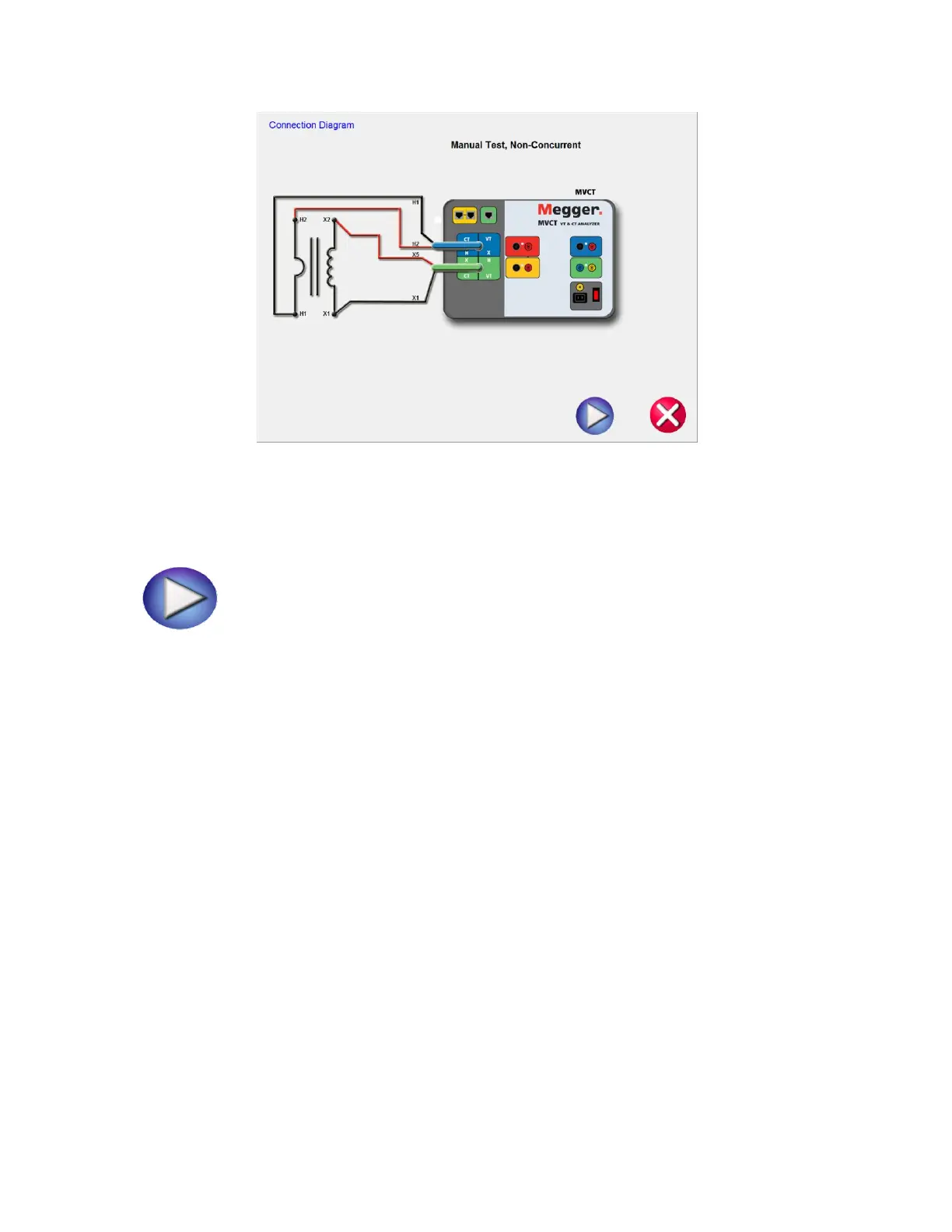
Figure 91 CT Manual Test Connection Diagram
12. Ensure the MVCT is properly connected.
13. Begin the test by selecting the Blue play button.
14. The MVCT will display:
Secondary (X) Voltage: The applied secondary test voltage is displayed on the screen in digital
readout form.
Primary (H) Voltage: The measured primary voltage is displayed on the screen in digital readout
form.
Secondary(X) Current: The secondary current is displayed for user reference to monitor while
performing ratio and saturation tests.
15. Ramp the voltage up and down by turning the knob on the integrated display or selecting the
up/down arrows on a PC
16. At the desired voltage level select the Record Button and the secondary voltage and current levels
will stored and then this point will be graphed into a log-log format.
17. This Manual Test allows the user to manual create saturation curves.