33
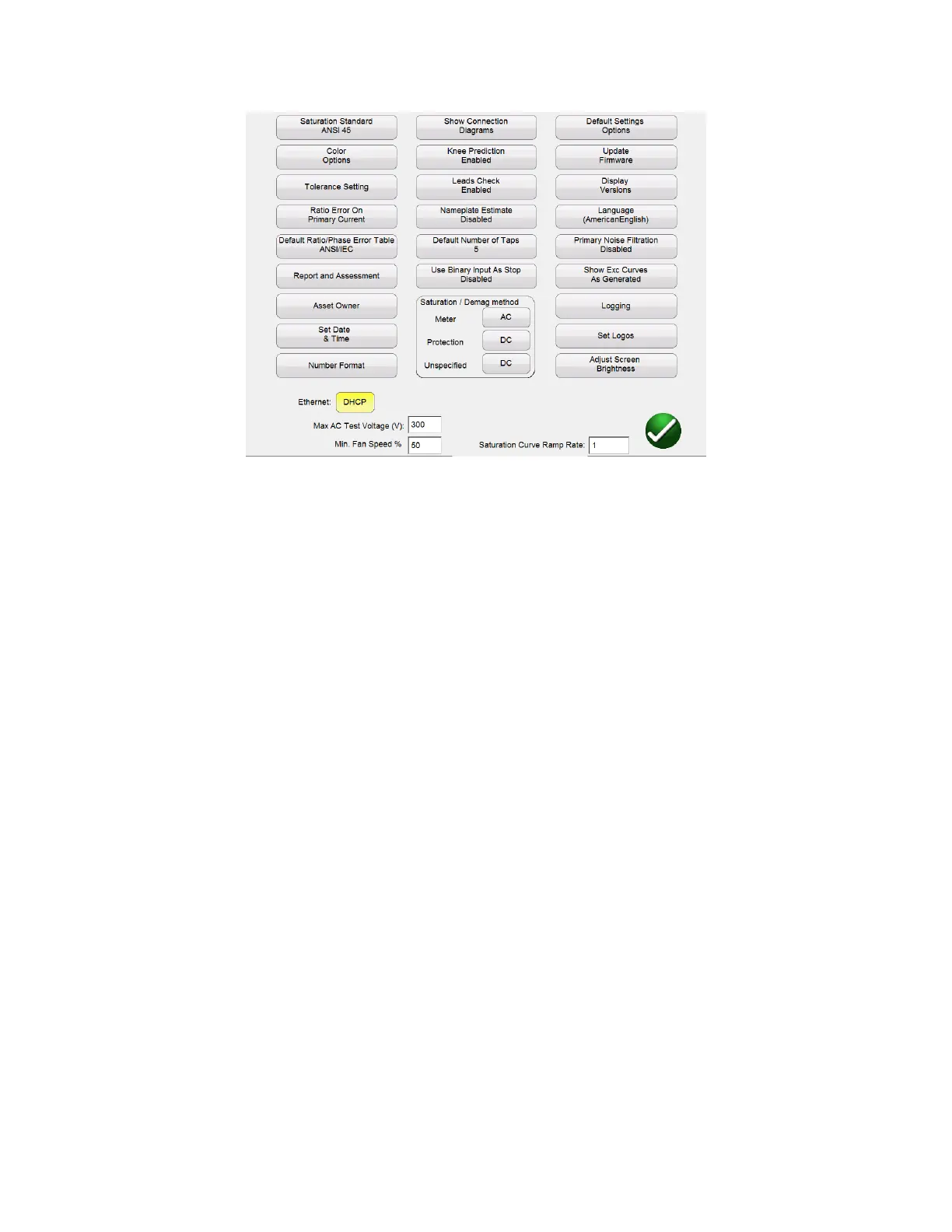
Figure 13 Device Settings – CT Testing
Within this screen all device settings are visible. However, only the settings that apply to the current
mode of testing will be accessible. By selecting the appropriate button, the user can:
Saturation Standard: Select between ANSI 45, ANSI 30, IEC 60044-1, IEC6044-6, or IEC61869
Color Options: Select the desired colors for Background color, Grid color, Label color,
Knee Marker color, and Saturation traces
Tolerance Settings: Displays the ratio and phase error limits specified by either ANSI or IEC
Ratio Error on Primary/Secondary Current: Allows user to select whether the ratio error is
displayed on Primary Current ( 101:5) or displayed on Secondary Current ( 100:4.99)
Default Ratio/Phase Error Table: Allows user to set the default ratio/phase error table
that will be calculated for a CT. The button will toggle between ANSI/IEC table which will give
the error for 1,5,10,20,50,100, 120, and 200% of primary current or the IS table which will give
the error for 20,40, and 80% of primary current
Report and Assessment: Allows the user to customize the report. He can select whether
or not to display the ratio and phase error tables, the parallelograms, and whether or not to
include an assessment. Several CT parameters will be evaluated. Both IEC and ASNI define
different parameters for the different classes of CT. Thus the parameters assessed will vary
depending upon the class of CT selected. Please note for this functionality to work, it must first
be enabled, the CTs nameplate information must be completed, and then the Ct must be fully
tested including saturation/excitation, ratio, phase, and winding resistance. Once the test is
complete, the CT values will be assessed in the 3
rd
page of the report and the CT will be given a
Pass/Fail assessment.