103
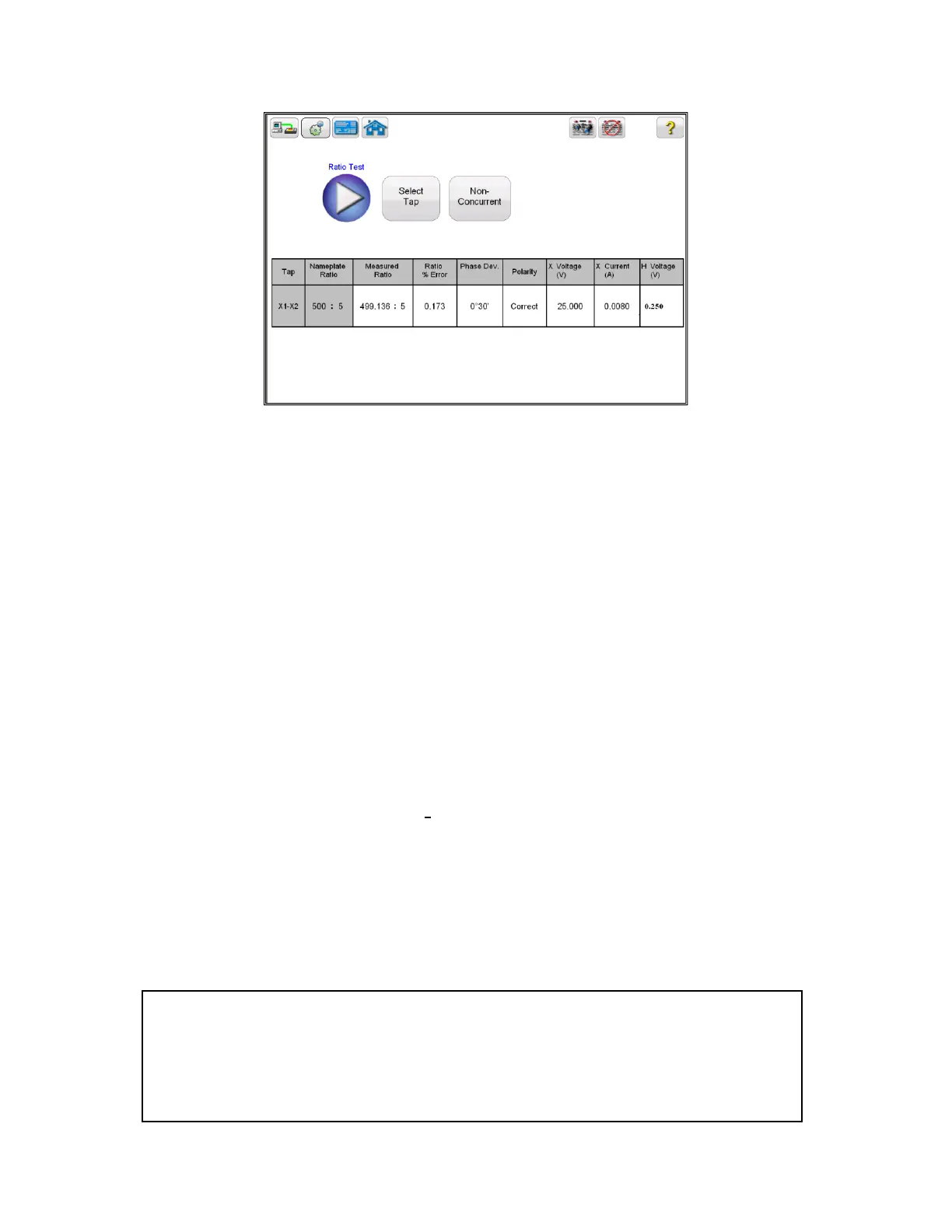
Figure 73 CT Ratio Test Results – Non Concurrent
Polarity: Unit automatically determines the polarity connections and displays the
result as either polarity Correct or Incorrect. The phase angle deviation between the
secondary and primary voltage is also displayed along with polarity.
The ratio is defined as the number of turns in the secondary as compared to the
number of turns in the primary.
N2/N1=V2/V1
Where,
N2 and N1 are no. of turns of secondary and primary windings respectively
V2 and V1 are the secondary and primary side voltage readings respectively.
A suitable voltage, below saturation is applied to the secondary of the CT under test
and primary side voltage is measured to calculate the turns ratio from above
expression.
6.4 CT Winding Resistance Test:
6.4.1 Method 1 – Concurrent
Refer to the safety instructions first before use of the equipment.
1. Verify the Power ON/OFF switch is OFF. Power the test set from a suitable source of power (95-
265 V50/60 Hz).
2. Connect the ground wing nut to a suitable ground.
WARNING
There is always the possibility of voltages being induced at the terminals of a test specimen
because of proximity to high voltage energized lines. A residual static voltage charge may
also be present at these terminals. Ground each terminal to be tested with a safety ground
stick, before making connections.