107
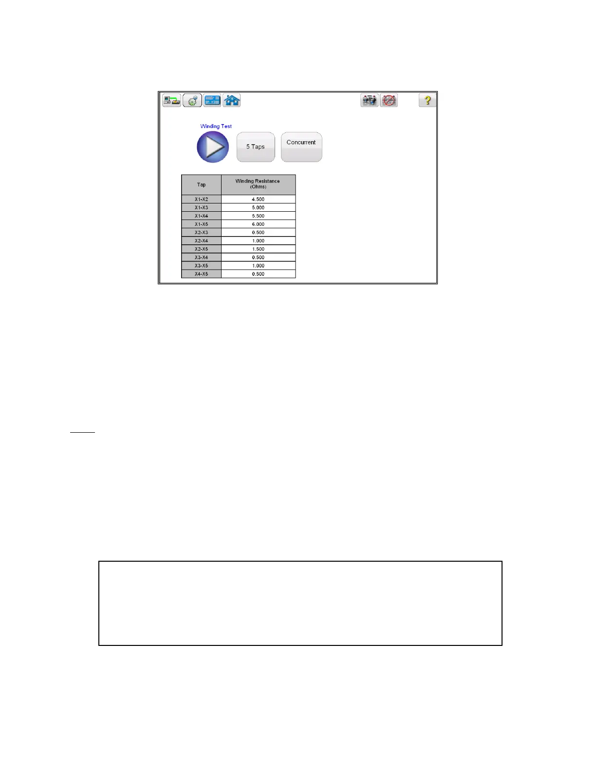
Figure 77 CT Winding Results - Concurrent
Winding resistance test is used to determine if the dc resistance of the CT secondary winding is
within specification or not. A DC current is applied and voltage is measured to determine the
winding resistance for the selected tap. After measurement winding resistance is displayed in
digital format on the screen.
Note: A CT should be demagnetized after running the winding resistance test. Run a saturation test to
demagnetize the CT at the completion of all winding resistance tests.
6.4.2 Method 2 – Non Concurrent or Testing a Single Tap
Refer to the safety instructions first before use of the equipment.
1. Verify the Power ON/OFF switch is OFF. Power the test set from a suitable source
of power (95-125 or 195-265 V50/60 Hz).
2. Connect the ground wing nut to a suitable ground.
WARNING
There is always the possibility of voltages being induced at the terminals of a test
specimen because of proximity to high voltage energized lines. A residual static voltage
charge may also be present at these terminals. Ground each terminal to be tested with a
safety ground stick, before making connections.