58
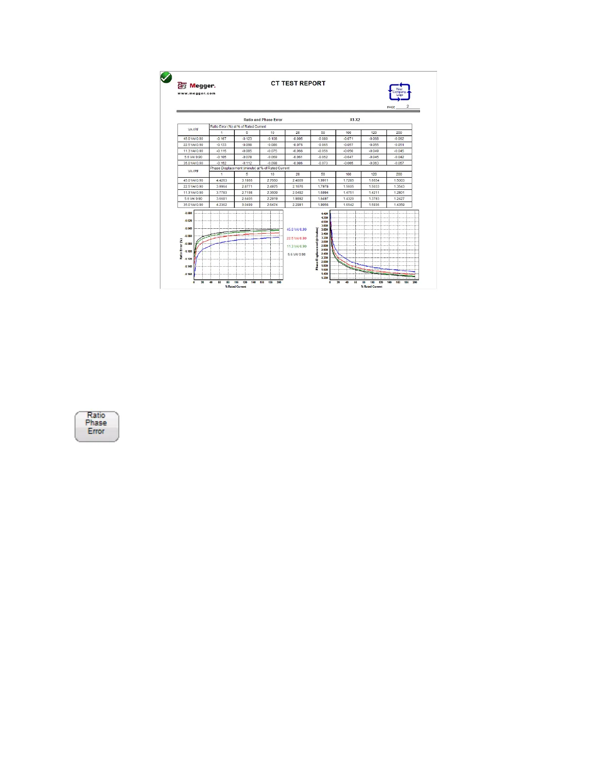
Figure 30 Ratio and Phase Error Tables
In device settings the user can configure the report to contain any of the following: Ratio Error Table,
Ratio Error Graph, Phase Displacement Table, Phase Displacement Graph and assessment of the CT
under test. If any of these have been included in the report, after testing the CT, the user can use the
Ratio Phase Error Button to control the number of taps displayed.
Ratio & Phase Error Button
The “ Ratio & Phase Error “ button will be visible within the report only if the user selected them in
device settings, has entered the correct nameplate information and has also executed the required
tests. First the user must enter the following CT Name Plate information:
CT Type either Metering or Relaying
Accuracy Class
Burden and/or VA
Ratio
Then if the user executes the required tests of the CT
Saturation/Excitation
Ratio
Winding Resistance