23
CT’s are expected to provide the secondary output current based upon their accuracy class. If a CT is not
properly sized based upon secondary loop burden, it may result in decrease in CT secondary current.
Burden test is important to verify that CT is supplying current to a circuit with burden that does not
exceed its burden rating.
A detailed description of how to perform a burden test with MVCT is given in the test procedure.
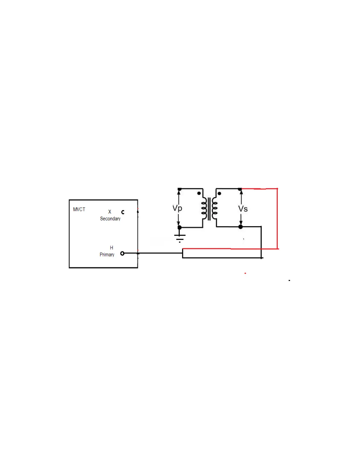
3.2.6 Secondary Winding Resistance
The transformer winding resistances can be measured by current voltage method. In this method of
measurement of winding resistance, the MVCT injects test current into to the secondary LV winding and
corresponding voltage drop across the winding is measured. By applying simple Ohm's law i.e. R
x
= V ⁄ I,
one can easily determine the value of resistance.
4.0 Powering System
4.1. Initial Start Up
1. If the unit was ordered with an integrated display, using the Ethernet cable supplied with the
unit connect the STVI Ethernet Port on the MVCT unit to the Ethernet port on the lower front of
the display module
2. Before connecting power to the unit, make sure the MVCT POWER ON/OFF Switch is in the OFF
position (0). Plug the unit line cord into an appropriate power source and turn the POWER
ON/OFF Switch to ON (I). As the MVCT unit goes through its power up sequence, in about a
minute the display power up screen will appear, then the test configuration screen will appear.