114
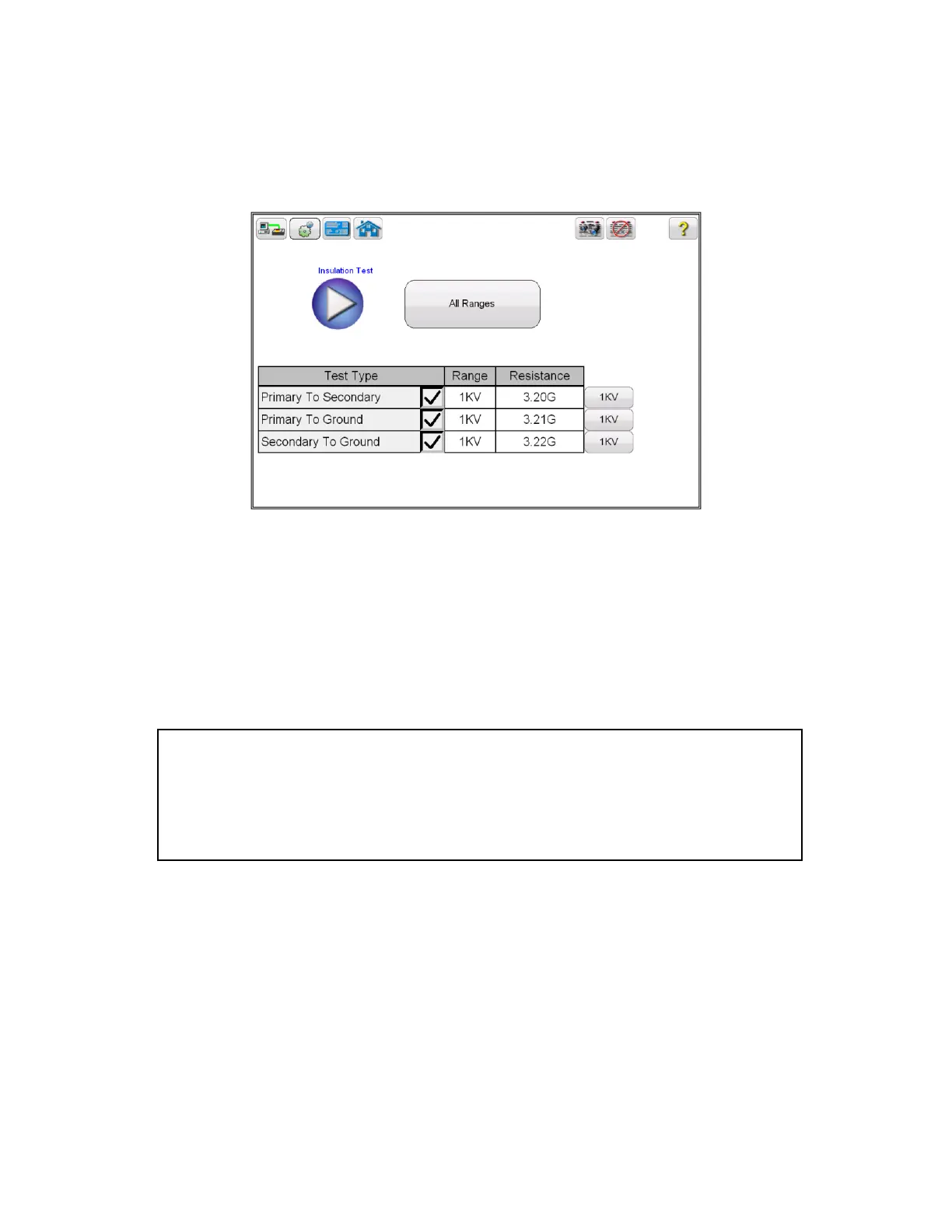
15. Upon completion of all tests the results will be displayed in the test screen or in a
test report.
Figure 85 CT Insulation Test Results
6.6 Burden Test
Refer to the safety instructions first before use of the equipment.
1. Verify the Power ON/OFF switch is OFF. Power the test set from a suitable source
of power (95-125 or 195-265 V50/60 Hz).
2. Connect the ground wing nut to a suitable ground.
3. Disconnect the burden on de-energized CT.
Note: Refer to the Burden Test connection diagram below for more details.
4. Connect the test set primary binding posts H1 and H2 to either side of the CT burden. and H2.
5. On test lead set labeled CT X/S connect the high voltage connector color coded green to the MVCT
high voltage connector that is color coded green and labeled SOURCE Voltage. Use the red
alignment marks on the 2 connectors to properly align them before connecting.
6. On test lead set labeled CT H/P Connect the high voltage connector color coded blue to the MVCT
high voltage connector that is color coded blue and labeled MEASUREMEMT. Use the red alignment
mark on the 2 connectors to properly align them before connecting
WARNING
There is always the possibility of voltages being induced at the terminals of a test
specimen because of proximity to high voltage energized lines. A residual static voltage
charge may also be present at these terminals. Ground each terminal to be tested with a
safety ground stick, before making connections.