115
7. On test lead set labeled CT X/S connect the test lead binding posts X1 and X5 to either side of the
burden of the CT
8. On test lead set labeled CT H/P connect the test lead primary binding posts H1 and H2 to CT primary
bushings H1 and H2.Observe the polarity marks on the CT (H1 on the test set is polarity terminal).
9.
10. Turn Power ON/OFF switch to ON.
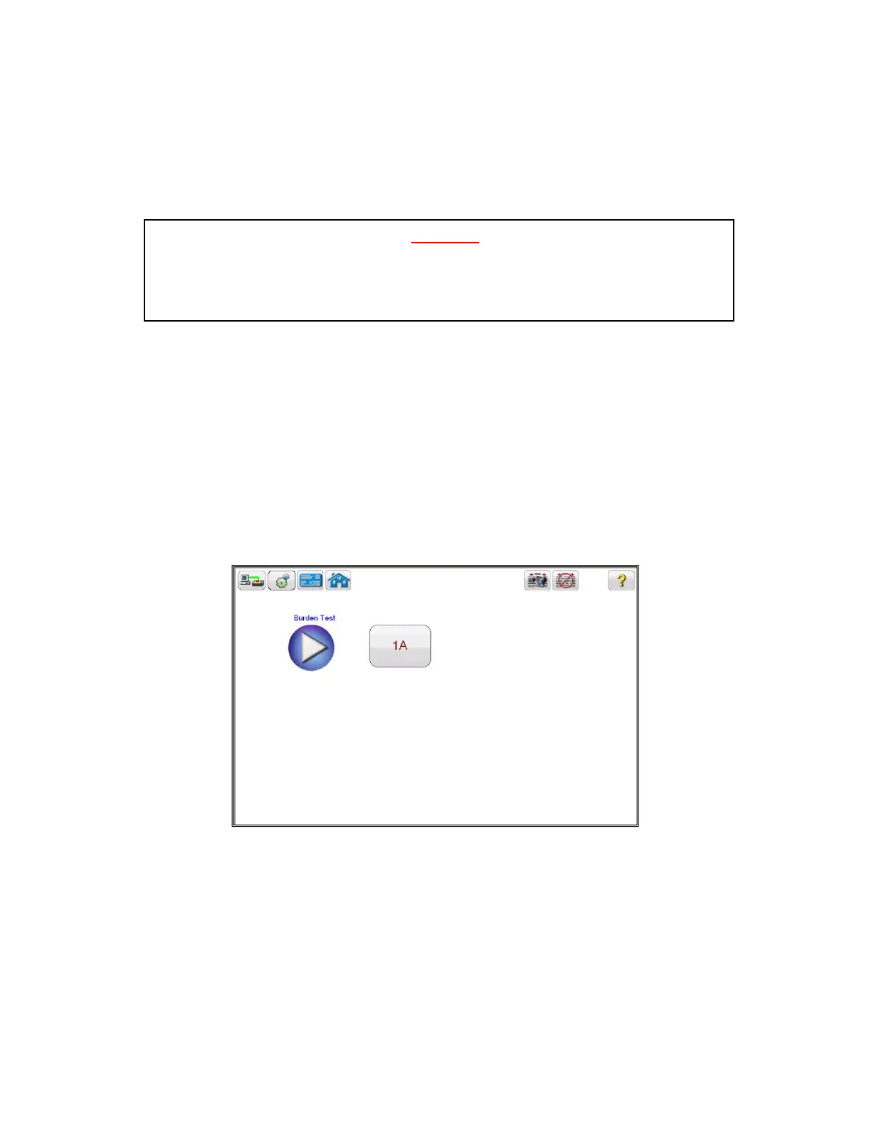
11. After the boot up, in the Home Screen select the “Burden Test” button
12. In the Burden test screen, select the appropriate test current of either
1 Amp or 5 Amp based upon secondary current rating of the CT under test
Figure 86 CT Burden Test Screen
13. Select the play button and a connection diagram will appear showing how to correctly connect the
MVCT to the CT
WARNING
The MVCT produces high voltages and currents during the performance of tests. DO NOT
TOUCH connector clips or test leads while the MVCT is performing a test.