125
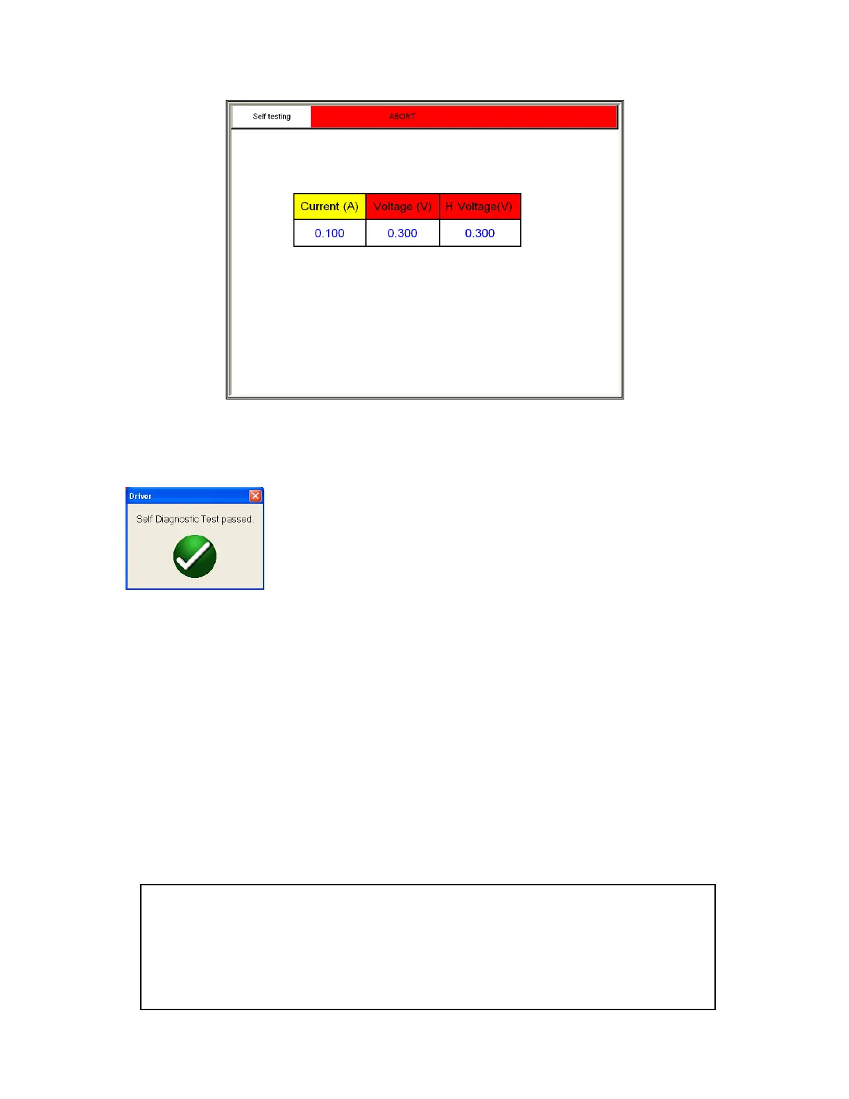
Figure 95 CT Self Diagnostic Test Screen
9. After the unit has checked the voltage and current generators and meters are working properly, the
user will be advised the unit has passed or failed the test
7.0 Testing VT’s with MVCT
7.1 Running a Complete Test of VT and Test Plan Creation
Refer to the safety instructions first before use of the equipment.
1. Verify the Power ON/OFF switch is OFF. Power the test set from a suitable source of power (95-265
V50/60 Hz).
2. Connect the ground wing nut to a suitable ground.
WARNING
There is always the possibility of voltages being induced at the terminals of a test
specimen because of proximity to high voltage energized lines. A residual static voltage
charge may also be present at these terminals. Ground each terminal to be tested with a
safety ground stick, before making connections.