138
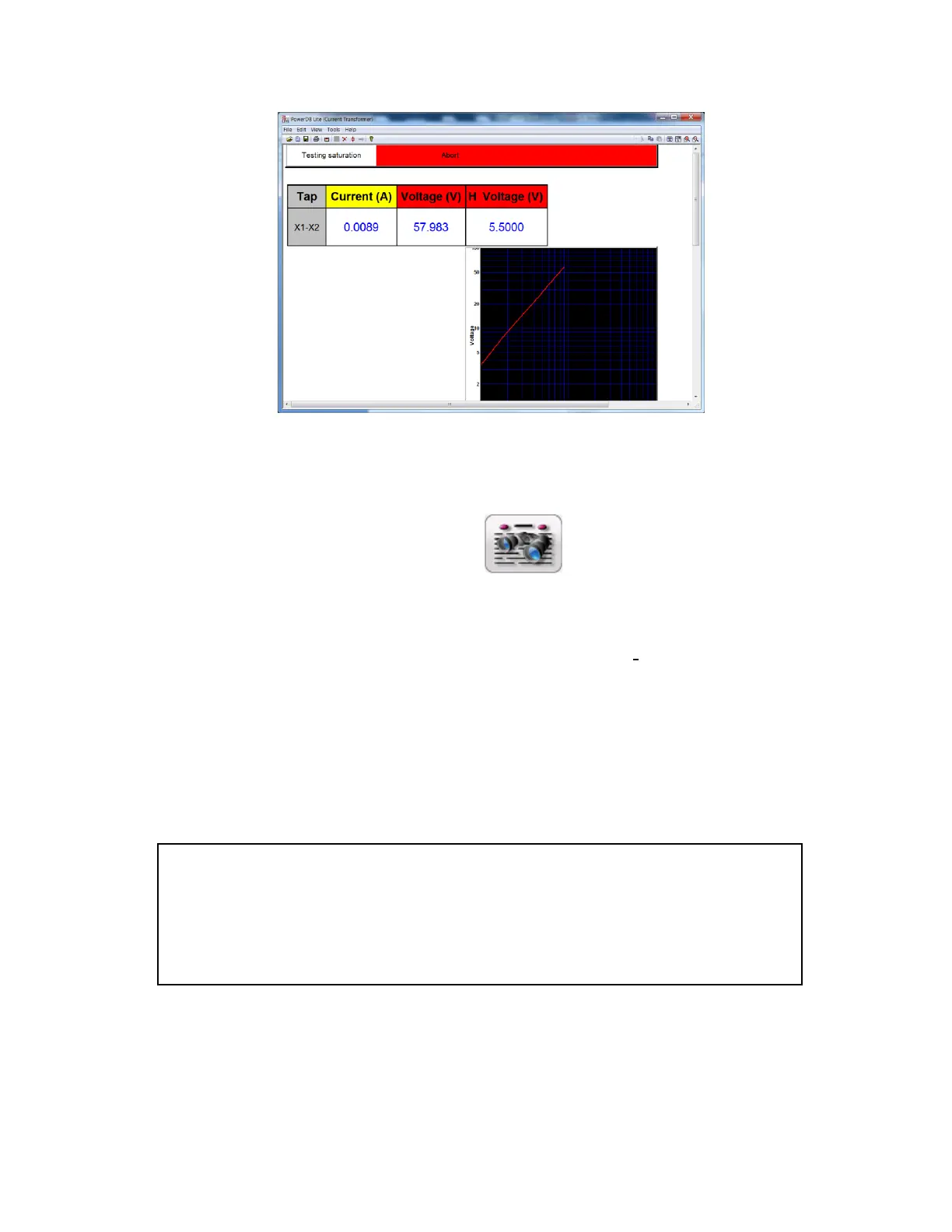
Figure 110 VT Saturation Test Screen
12. Upon completion of test the results will be displayed in the test screen or it can be displayed
in a test report by selecting the view report button
7.4 Testing Voltage Transformer Winding Resistance :
Refer to the safety instructions first before use of the equipment.
1. Verify the Power ON/OFF switch is OFF. Power the test set from a suitable source
of power (95-125 or 195-265 V50/60 Hz).
2. Connect the ground wing nut to a suitable ground.
3. On test lead set labeled VT H/P connect the high voltage connector color coded green to the
MVCT high voltage connector that is color coded green and labeled SOURCE Voltage. Use the
red alignment marks on the 2 connectors to properly align them before connecting.
WARNING
There is always the possibility of voltages being induced at the terminals of a test
specimen because of proximity to high voltage energized lines. A residual static voltage
charge may also be present at these terminals. Ground each terminal to be tested with a
safety ground stick, before making connections.