139
4. On test lead set labeled VT X/S Connect the high voltage connector color coded blue to the
MVCT high voltage connector that is color coded blue and labeled MEASUREMEMT. Use the red
alignment mark on the 2 connectors to properly align them before connecting
5. On test lead set labeled VT H/P connect the test lead binding posts H0 and H1 to secondary of
the voltage transformer on the X0 and X1 terminals. Observe the polarity marks on the VT (HO
on test set is polarity terminal).
6. On test lead set labeled VT X/S connect the test lead binding posts X0 and X1 to VT secondary
terminals H0 and H1. Observe the polarity marks on the VT (X0 on the test set is polarity
terminal).
7. Turn Power ON/OFF switch to ON
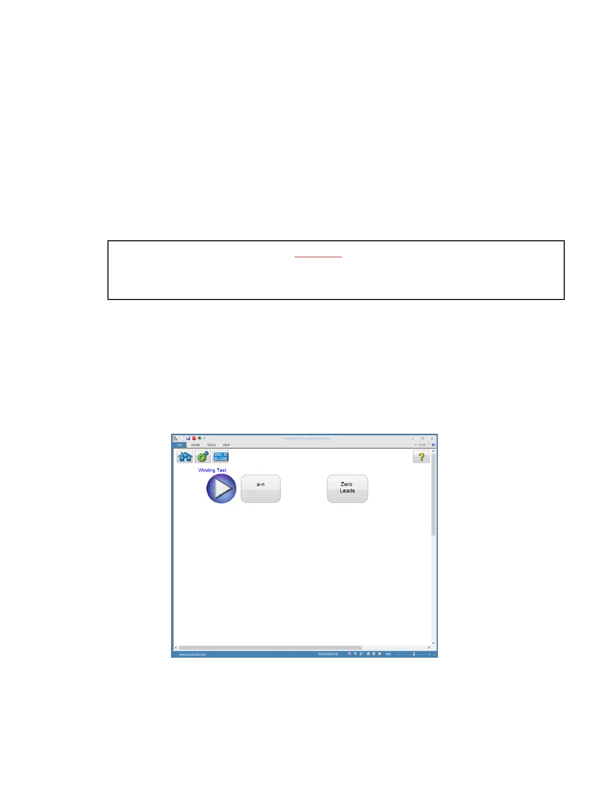
8. After boot up, in the Home Screen set the MVCT to VT Testing mode and select the “Winding
Resistance Test” button.
Figure 111 VT Winding Test Screen
WARNING
The MVCT produces high voltages and currents during the performance of tests. DO NOT TOUCH
connector clips or test leads while the MVCT is performing a test.