COOLING
90-884294 OCTOBER 2001
Page 4B-7
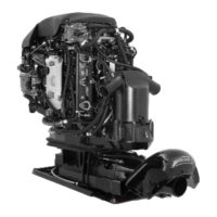
3 Liter Work/225 EFI/250 EFI Water Flow Diagram
1. Water Inlet
2. Water Pump
3. Wall of Water – If water level height is insufficient, water pump may draw in air resulting in an overheated engine.
4. Strainer – Exhaust cooling water.
5. Main Water Feed to Powerhead from Water Tube
6. Rubber Water Dams – If missing may result in uneven cooling of cylinders and scuffed pistons.
7. Cylinder Head Cover – Removed from head for illustration, normally part of head casting.
8. Thermostat (2) 143 °F (61.7 °C) – If stuck closed, engine will overheat at low speed. If stuck open, engine will not warm up at idle speed.
9. Poppet Valve – Controls water flow at high RPM. If poppet valve is stuck open at low rpm, the engine will not reach proper operating temperature (run cold) and will run rough at idle.
10. Primary water discharge into driveshaft housing.
11. Water discharge into exhaust relief passage.
12. Water Pressure Sensor
13. Check Valve for powerhead flush
14. Water passing through thermostats dump into adaptor plate, then discharges down the exhaust.
15. Tell-Tale Outlet
16. Excess water from wall of of water around exhaust bucket exits around anodes.
17. Water exiting exhaust discharge.
7
7
14
59162
1
17
16
2
3
4
5
6
8
8
9
1
16
12
13
14
15
10
11
11
17
1
1

 Loading...


