IGNITION
90-884294 OCTOBER 2001 Page 2A-29
EFI Detonation Control System (200 Work Model only)
The detonation control circuit is located in the ECM. This circuit monitors 2 detonation
(knock) sensors; 1 each located in each cylinder head. When detonation is initially de-
tected, timing is retarded. If detonation continues, fuel mixture is richened.
Use DDT to monitor Knock Volts (Press Keys 1, 3, 1)
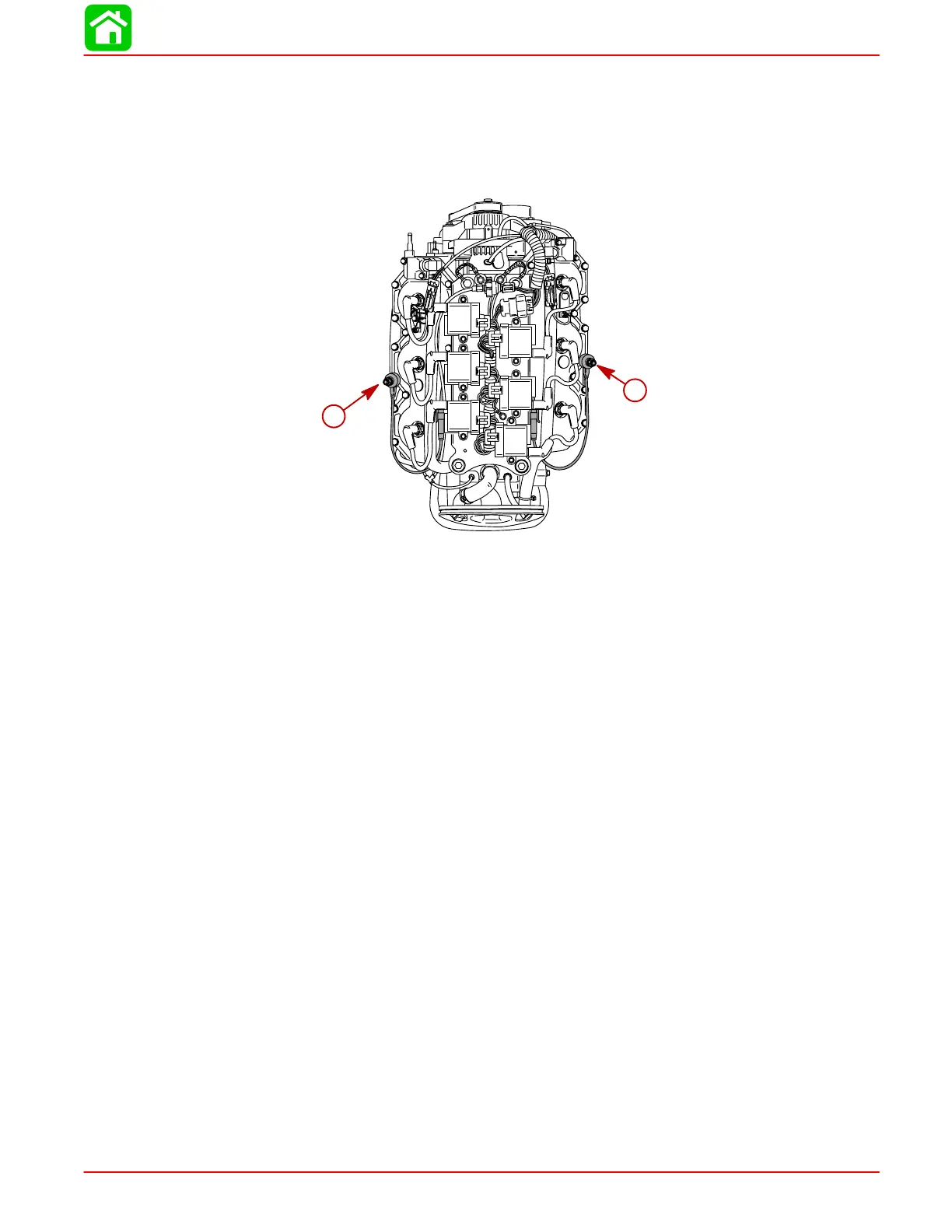
59034
a
a
a-Detonation Sensor (1 per cylinder head)
Detonation Circuit Test
1. Turn key switch to RUN position (do not start engine). With Digital Diagnostic Terminal
connected to engine, DDT should indicate over 6 volts for knock voltage output.
2. Start engine and run at idle. DDT indicated knock voltage output should drop below
1.0 volt. If voltage does not drop below 1.0 volt, knock circuit within ECM is defective.

 Loading...

