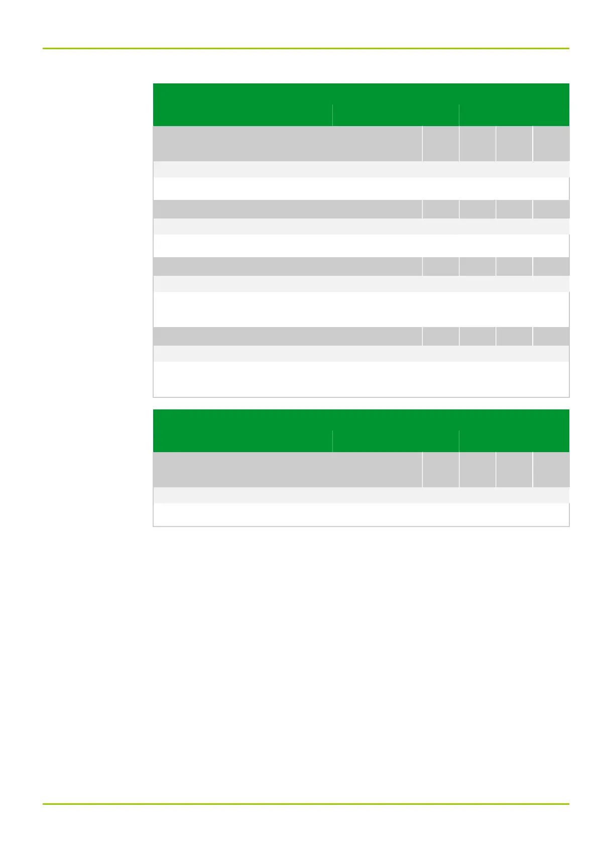
Parameter Address
Default Min Max Unit Logic Diagram
Binary and analog
output
OUTP: Reset latch. USER
021 009
0: don't execute Fig. 3-29, (p. 3-45)
[spacer]
Reset of latched output relays from the user interface.
[spacer]
OUTP: Relay assign. f.test
003 042
060 000: MAIN: Without function Fig. 3-30, (p. 3-46)
[spacer]
Selection of the relay to be tested.
[spacer]
OUTP: Relay test
003 043
0: don't execute Fig. 3-30, (p. 3-46)
[spacer]
The relay selected for testing is triggered for the duration set at OUTP: Hold-
time for test.
[spacer]
OUTP: Hold-time for test
003 044
1 1 10 s Fig. 3-30, (p. 3-46)
[spacer]
Setting for the time period for which the selected output relay is triggered for
functional testing.
Parameter Address
Default Min Max Unit Logic Diagram
Measured data
output
MEASO: Reset output USER
037 116
0: don't execute Fig. 3-33, (p. 3-48)
[spacer]
Resetting the measured data output function.
8 Information and Control Functions
P631
P631/EN M/R-11-C // P631-310-650 8-87