1-4 MINI Hawk High Performance Imager User’s Manual
Position Imager and Symbol
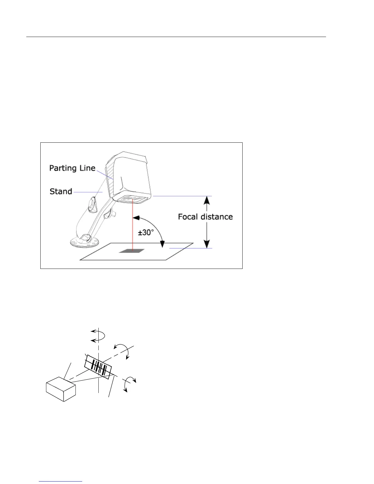
Step 3 — Position Imager and Symbol
• Position the imager at a focal distance between 2 and 6 inches from the symbol.
• Tip the imager relative to the symbol to avoid the glare of direct (specular) reflection. The
case parting line should be perpendicular to the plane of the symbol by either pitching the
symbol or the imager as shown.
• Position the imager in a place with as little ambient light as possible.
• Symbols can be rotated (tilted) at any angle; however, for best results symbols should
be aligned with the FOV (field of view).
• In the case of linear symbols, aligning the bars in the direction of their movement (“ladder”
orientation) will minimize the chances of blurring, and will produce better reads.
Important: Avoid excessive skew or pitch. Maximum skew is ±30°; maximum pitch is
±30°. The illustration below shows skew axis, pitch axis, and tilt axis.
Note: For accuracy of testing and performance, Microscan recommends using a mounting
arm adapter kit. Contact your Microscan sales manager for details about mounting arm
adapter kits and other accessories.
Imager and Symbol Orientation
Pitch
axis
Bar code
label
Tilt
axis
axis
Scan line
Scanner
Pitch
Tilt
Skew
Symbol
Reader