A-6 MINI Hawk High Performance Imager User’s Manual
Electrical Specifications
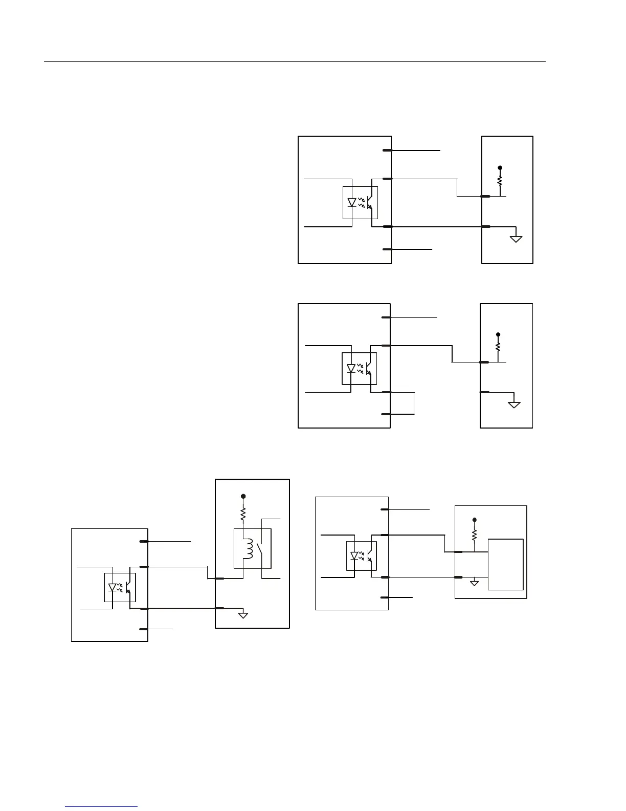
Output Circuit Examples
Fully Optoisolated
This circuit is fully optoisolated and is the
recommended configuration. It allows
the
user to apply 1 to 28 VDC to the circuit.
Caution: The maximum current that can
pass through the optoisolator is 100mA.
Not Optoisolated, Imager Grounded
In this diagram, power is applied externally,
but the scanner’s power ground is used
to complete the circuit. This setup
involves some risk to the optoisolator if
excessive voltages are applied.
Caution: The maximum current that can
pass through the optoisolator is 100mA.
Additional Output Circuit Examples
1to28V
Input
Scanner
Output
Power ground
Outputs (+)
Power (+)
Outputs (–)
1to28V
Input
Scanner
Output
Power ground
Power (+)
Outputs (–)
Outputs (+)
RELAY
Scanner
Output
Power ground
Outputs (+)
Power +
Outputs (–)
1to28V
Secondary Relay
PLC
Isolated
V
PLC
GND
PLC
Input
Scanner
Output
Power ground
Outputs (+)
Power +
Outputs (–)