116
Configuration
9.1 QX-mini Main or Booster Board Switch Locations
The QX-mini requires a unique address for each board to be identified by other devices and
FACPs. The DIP switch SW1 allows the identification of each QX-mini main or Booster board
when wired up together. Once properly addressed, QX-mini boards will correctly route control
and audio signals to the proper destinations or zones. It permits the correct zone call or control
hierarchy for the remote microphones.
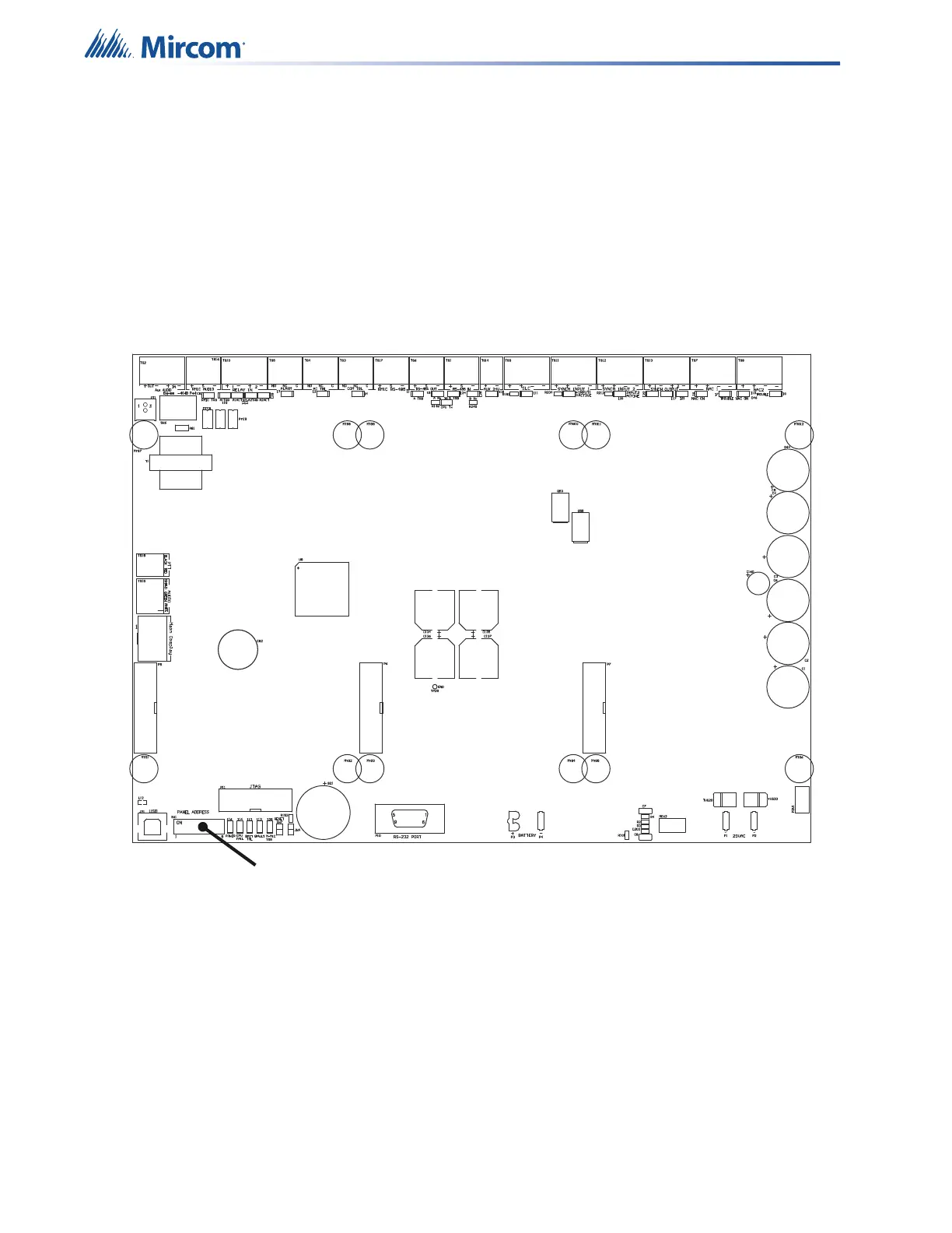
The following diagram shows the location of the one DIP switch (SW1) used to configure the
QX-mini.
Figure 68 QX-mini DIP Switch location