118
Configuration
9.2 DIP Switch Configuration
The Panel Address is set using the DIP switch, located on the bottom left of the QX-mini or
QX-mini-BP main boards, and using the configurator software.
Configuration is done by setting DIP switch SW 1 to the desired address. Addresses can be
set to any value from 1 to 6 but it MUST match the software configurator settings.
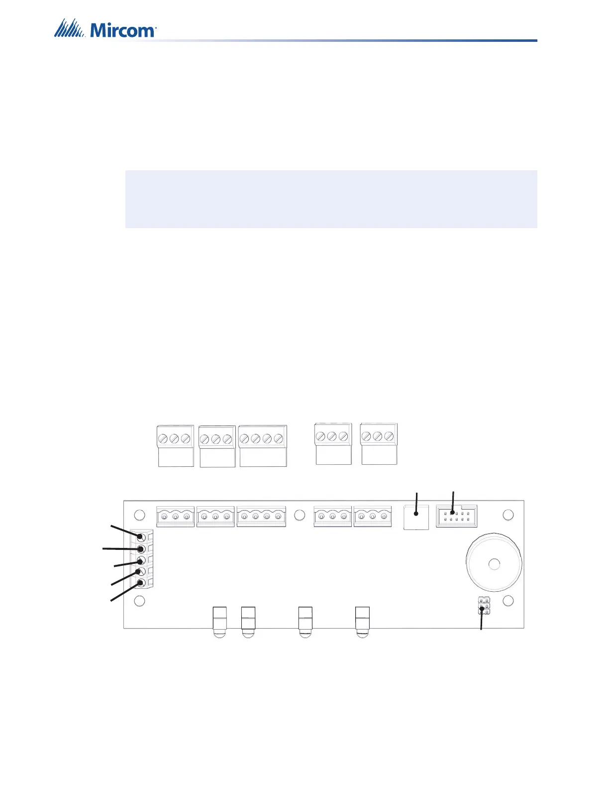
9.3 Remote Mic or LOC Switch Locations and Configuration
The QX-mini-RM and QX-mini-LOC board have one rotary switch used to set the RS-485
address on the remote microphone. Rotary switch SW2 is used to set the value for the RS-485
address.
See the following figure for the positions of these switches on the remote microphone board.
In order to access the board on the QX-mini-RM, remove the cover plate from the remote
microphone.
Figure 70 QX-mini-RM and QX-mini-LOC board
Note: The Master Panel must have Panel ID# ‘1’ and the Factory Default of Panel ID of
0 will cause a Trouble indication.
P1
SW2
RS-485
24VDC
AUDIO
s
IN OUT IN
OUT
Black
Red
Shield
Green
White
IN OUT
TS6
TS4
TS5
TS3
TS1
TS2
P2
-
+
s
-
+
s
-
+
s
-
+
-
+
-
+