83
Indicators & Controls
5.1 Indicators and Controls
Indicators and controls on the QX-mini are found on the main display panel, the main board,
and the QAD-30 amplifier module. The main display panel has indicators (LEDs) that provide
status information and controls (buttons) for operating the QX-mini. For troubleshooting
purposes, there are LEDs located on the main board and on the QAD-30 amplifier module that
show Trouble, Alarm, Status, and Active for the main board components.
Indicators may be Yellow, Red, or Green. Indicators may illuminate continuously (steady), or
flash at the Trouble Flash Rate of 20 flashes per minute with a 50% duty cycle.
Controls are used to select zone(s), select a pre-recorded message, or to acknowledge a
trouble alert. There is also one DIP switch used for configuration.
5.2 Main Display LEDs and Controls
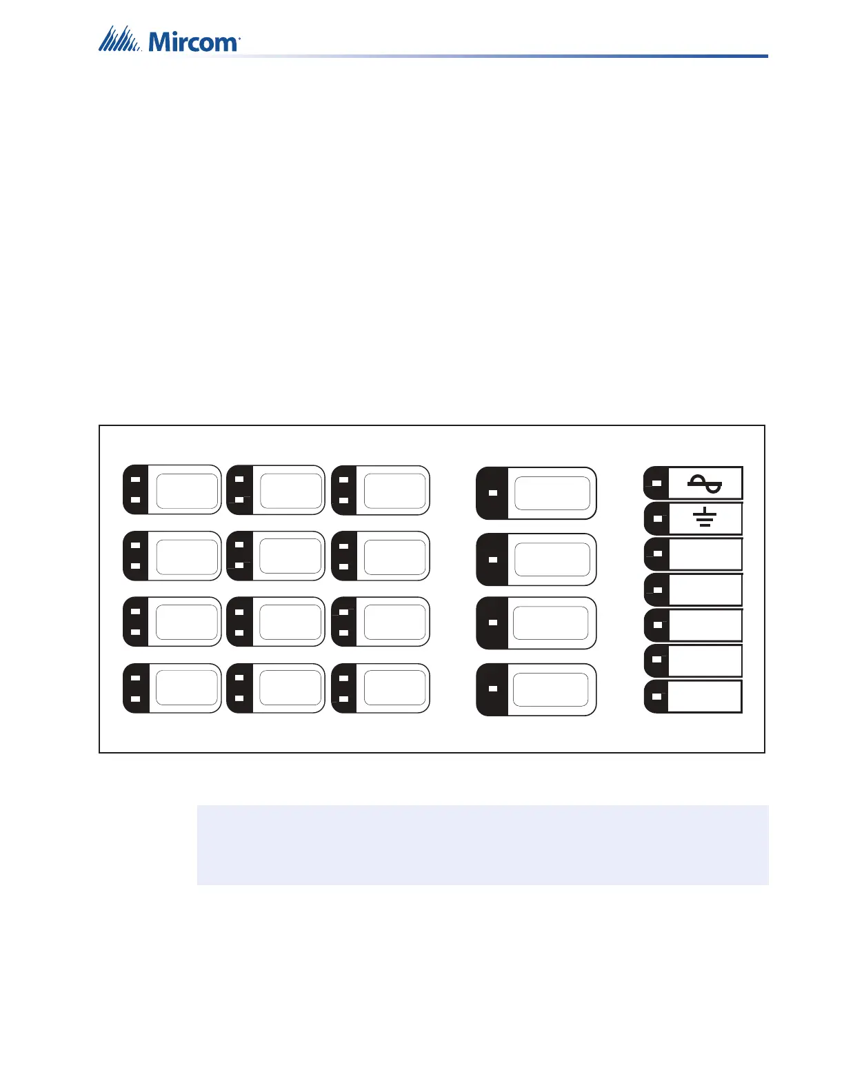
The main display panel indicators and controls are shown in Figure 56. This section describes
the purposes of these indicators and what the controls do.
Figure 56 The QX-mini main display panel
Note: Buttons are reprogrammable using the Configurator software.
CPU
MESSAGE
ACTIVE
ALARM
ACTIVE
PRE-TONE
ACTIVE
READY
TO PAGE
ALL
CALL
CLEAR
SELECTION
VISUAL
INDICATOR
TEST
BELL
CONTINUOUS
SLOW WHOOP
CONTINUOUS
TEMPORAL
TONE (CODE3)
Trouble /
Trouble Silence
ALERT
EVACUATION
FALSE
ALARM
ALARM
CLEARED
ZONE 1
ZONE 2
ZONE 3
ZONE 4