57
Installation
3.7 Remote Microphone Connections
Up to six optional QX-mini-RM Remote Microphones can be connected to each QX-mini. The
remote microphones communicate with the QX-mini through an RS-485 network bus. Power
for the remote microphones comes from the 24VDC terminal on the QX-mini main board.
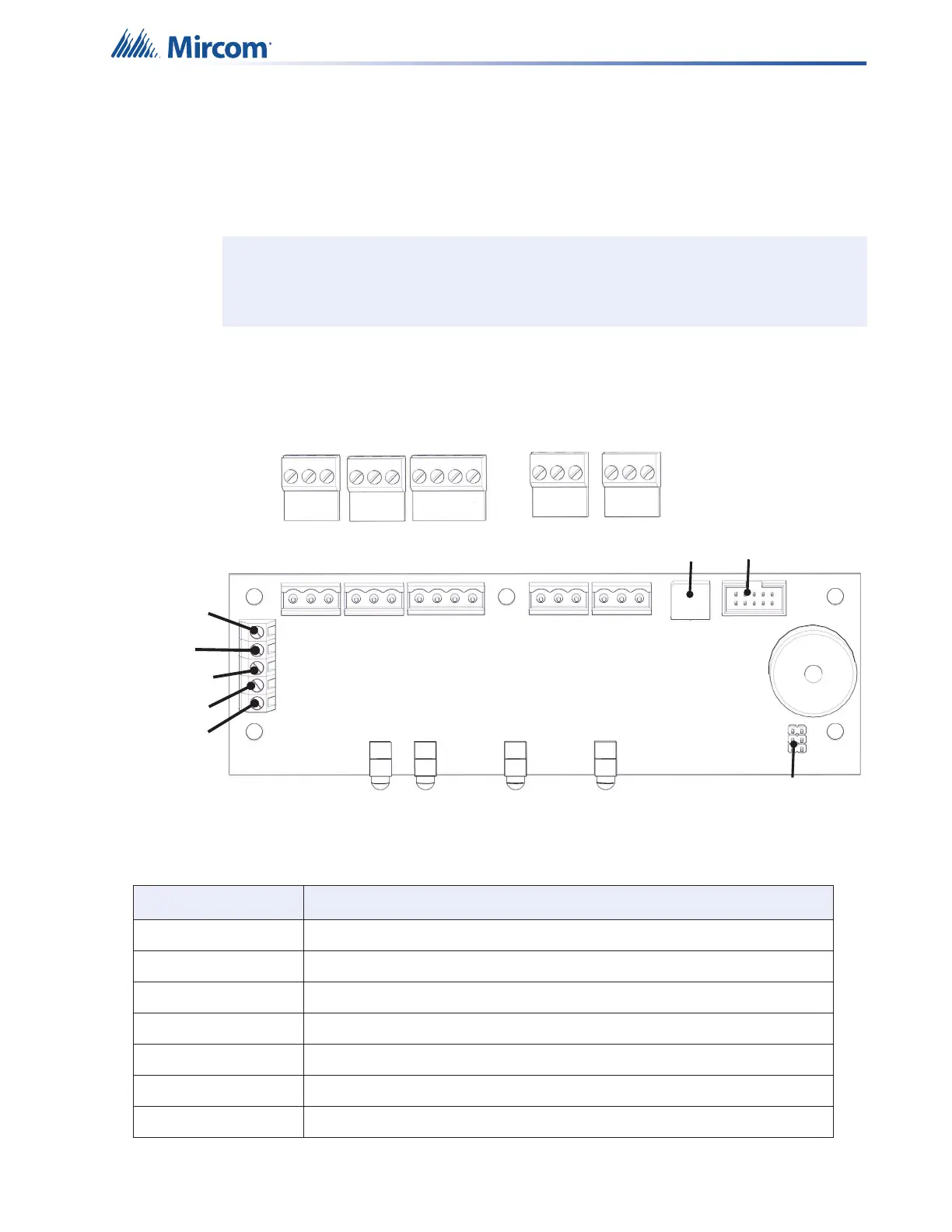
The terminals and jumper on the QX-mini-RM board are shown in Figure 28 and are described
in Table 9.
Figure 28 QX-mini-RM terminals and jumper locations
Note: RM not for use in Canada.
Table 9 QX-mini-RM terminals and jumper
Terminal/Jumper Description
SW2 Rotary switch for setting the RS-485 address on the QX-mini-RM.
TS1 RS-485 In terminal.
TS2 RS-485 Out terminal.
TS3 24 VDC In and Out terminal.
TS4 Audio In terminal from QX-mini or previous QX-mini-RM on the line.
TS5 Audio Out terminal to the next QX-mini-RM on the line.
TS6 Terminal for PTT microphone cable.
P1
SW2
RS-485
24VDC
AUDIO
s
IN OUT IN
OUT
Black
Red
Shield
Green
White
IN OUT
TS6
TS4
TS5
TS3
TS1
TS2
P2
-
+
s
-
+
s
-
+
s
-
+
-
+
-
+