45
Installation
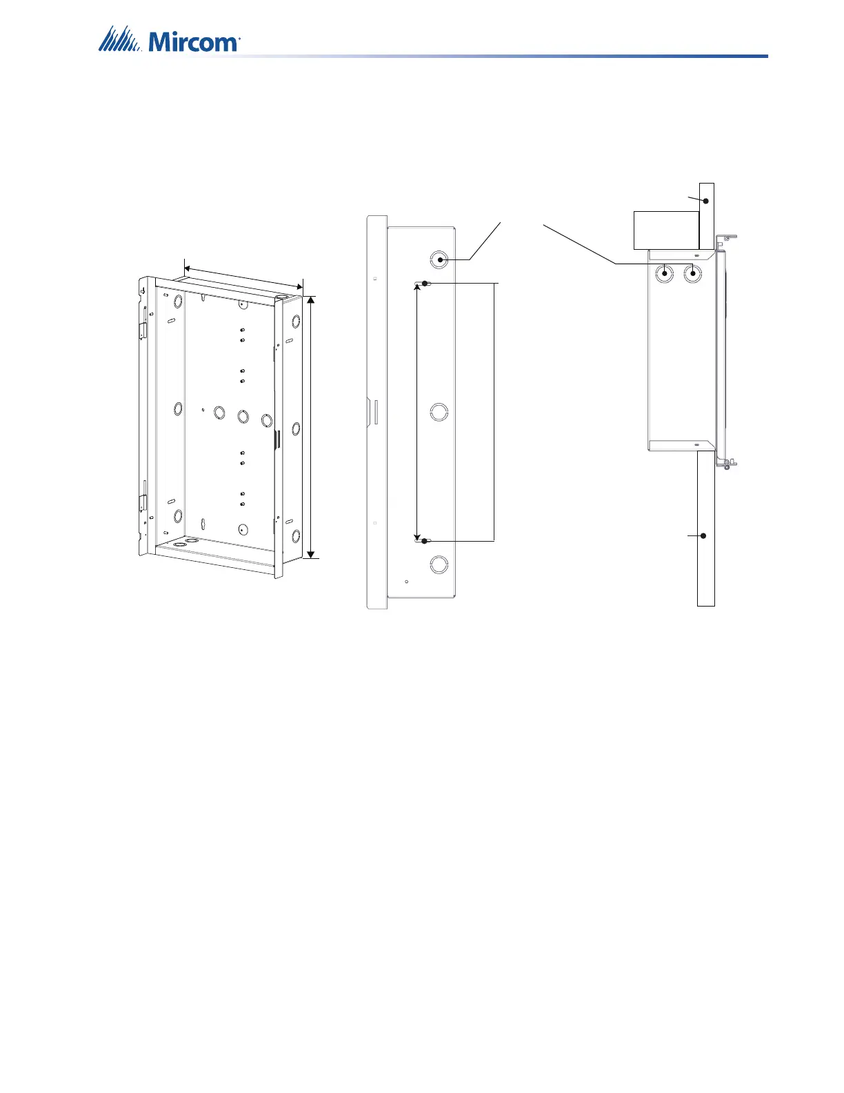
4. Find a suitable mounting location for the QX-mini-LOC, next to a wall stud or supporting
structure, and then mark an opening on the wall that matches the dimensions of the QX-
mini-LOC backbox.
Figure 17 QX-mini-LOC mounting holes
5. Cut an opening 0.1” larger than the opening marked in step 4, ensuring that one side is
aligned with the wall stud or supporting structure.
6. Attach the box using the necessary number of screws via the box’s side or back.
7. Tighten all screws.
8. Remove all necessary knockouts.
9. Attach the doors to the chassis and then secure the ground straps to the doors using the
wingnuts removed in step 3.
10. Secure the CH-1139A PCB bracket to the backbox using the screws removed in step 2.
11. Connect the ribbon cable from the main display to terminal P1 on the main board.
12. Connect the microphone cable to terminal TS6 on the main board.
Mount screws at
these points and
then tighten.
Front
Metal or
Wood Stud
Top ViewSide View
Conduit
Knockout
Wall
Wall
Back
Front
Back
QX-mini-LOC Backbox
Flush mount Footprint
12.5"
23”
16”