63
Wiring
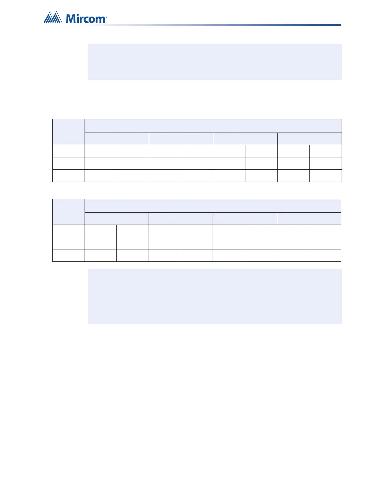
4.1.3 Wiring Tables for Speaker Circuits
Notes: Main Board NAC Circuits are rated for 2.5 Amperes each.
Maximum Voltage Drop Should Not Exceed 1.8 Volts.
Table 12 Wiring Table for 70V Speakers
Total
Power
Maximum Wiring Run to Last Device (ELR)
18AWG 16AWG 14AWG 12AWG
Watts ft m ft m ft m ft m
15 2500 762 4000 1219 6000 1828 8000 2438
30 1500 457 2500 762 4000 1219 6000 1828
Table 13 Wiring Table for 25V Speakers
Total
Power
Maximum Wiring Run to Last Device (ELR)
18AWG 16AWG 14AWG 12AWG
Wattsftmftmftmftm
15 625 190 1000 305 1500 457 2000 609
30 375 114 625 191 1000 305 1500 457
Notes: For each speaker zone, select the total zone power.
Distance shown is calculated to the last speaker, based on the worst case
scenario with all speakers lumped at the end.
Calculation is based on a 1dB power loss (20%) and a source of 70V or 25V.