117
Configuration
9.1.1 Setting the DIP switch
There is 1 bank of DIP switch bits on the QX-mini main board: SW1.
This DIP switch bank has 8 switches, numbered 1 to 8. Flipping a switch up places it in the ON
position. For the purposes of the configuration tables ON = 1 and OFF = 0. For an
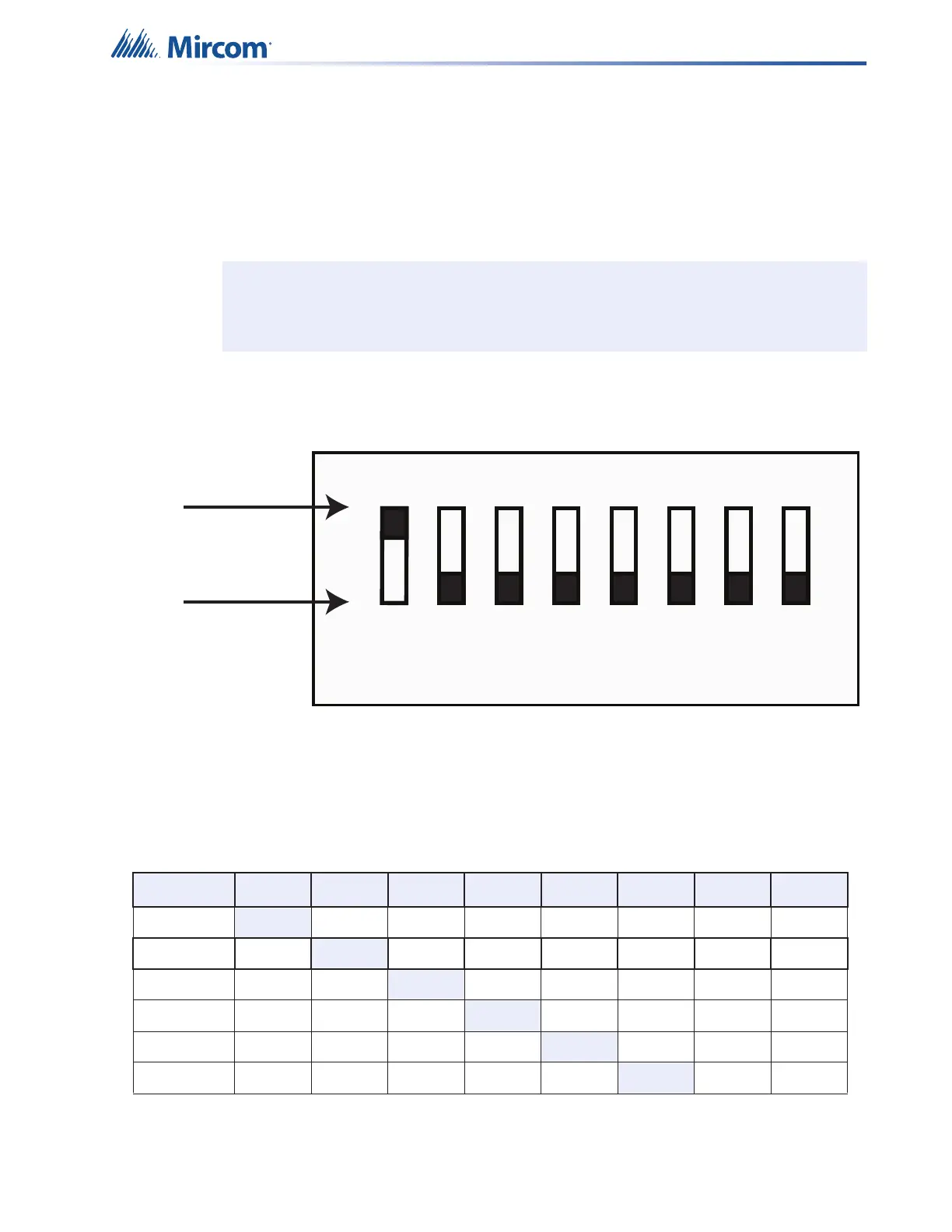
illustration of the DIP switch settings see Figure 69.
Figure 69 DIP switch positions
Note: The Master Panel must have Panel ID# ‘1’ and the Factory Default of Panel ID of
0 will cause a Trouble indication.
Table 18 Panel Address DIP Switch Bits
Panel ID Bit 1 Bit 2 Bit 3 Bit 4 Bit 5 Bit 6 Bit 7 Bit 8
1 ON OFF OFF OFF OFF OFF OFF OFF
2 OFF
ON OFF OFF OFF OFF OFF OFF
3 OFF OFF
ON OFF OFF OFF OFF OFF
4 OFF OFF OFF
ON OFF OFF OFF OFF
5 OFF OFF OFF OFF
ON OFF OFF OFF
6 OFF OFF OFF OFF OFF
ON OFF OFF
1 2 4 8
0
1
ON
OFF
3
5 6 7
1-0-0-0-0-0-0-01-0-0-0-0-0-0-0