65
Wiring
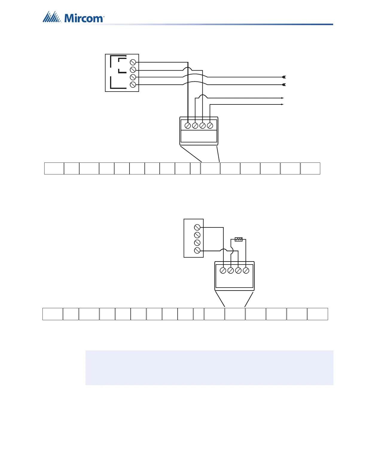
4.2.2 SLC Loop Wiring - Class A
Figure 33 SLC loop wiring - Class A
4.2.3 Synchronized Input from FACP Wiring - Class B
Figure 34 Synchronized input from FACP wiring - Class B
Sample setups:
• one QX-mini panel (generating synchronization) and three QX-mini-BP units
• one QX-mini panel and a FACP (regenerating synchronization from FACP) and two QX-
mini-BP units
• one QX-mini-BP unit (generating synchronization) and three QX-mini-BP units
Note: The inter-panel synchronization supports up to a total of four units.
-
+ +
-
SLC
FACP
ADDRESSABLE LOOP
CONNECTIONS
B
-
+
+
-
A
TO NEXT DEVICE
IN LOOP
FROM LAST
DEVICE IN LOOP
TS2TS16
TS10
TS5TS4TS3
TS17
TS6
TS1TS14
TS9
TS11
TS12 TS13 TS7TS8
AUX
AUDIO
RMIC
AUDIO
RELAY
IN
ALARM
AC
TBL
COM
TBL
RMIC
RS-485
RS-485 RS-485
INOUT
AUX
24V
SLC
SYNCH
SYNCH SYNCH
INPUT 2
INPUT 1
OUTPUT
NAC 1NAC 2
+OUT-
+IN-
+ 1 -
+ 2 -
+ 1 -
+ 2 -
+
S
-
+S
-
+S
-
+S
-
NO
NC
C
NO NC
C
NO
NC
C
+
-
+
-
+++
+
+
+
+
++
---
-
-
-
-
--
SYNCH SIGNAL FROM FACP
-
+ +
-
SYNCH INPUT1
NAC CIRCUIT
FROM FACP
-
+
+
-
MP-300 3.9K EOL
TS2TS16
TS10
TS5TS4TS3
TS17
TS6
TS1TS14
TS9
TS11
TS12 TS13 TS7TS8
AUX
AUDIO
RMIC
AUDIO
RELAY
IN
ALARM
AC
TBL
COM
TBL
RMIC
RS-485
RS-485 RS-485
INOUT
AUX
24V
SLC
SYNCH
SYNCH SYNCH
INPUT 2
INPUT 1
OUTPUT
NAC 1NAC 2
+OUT-
+IN-
+ 1 -
+ 2 -
+ 1 -
+ 2 -
+
S
-
+S
-
+S
-
+S
-
NO
NC
C
NO NC
C
NO
NC
C
+
-
+
-
+++
+
+
+
+
++
---
-
-
-
-
--