46
Installation
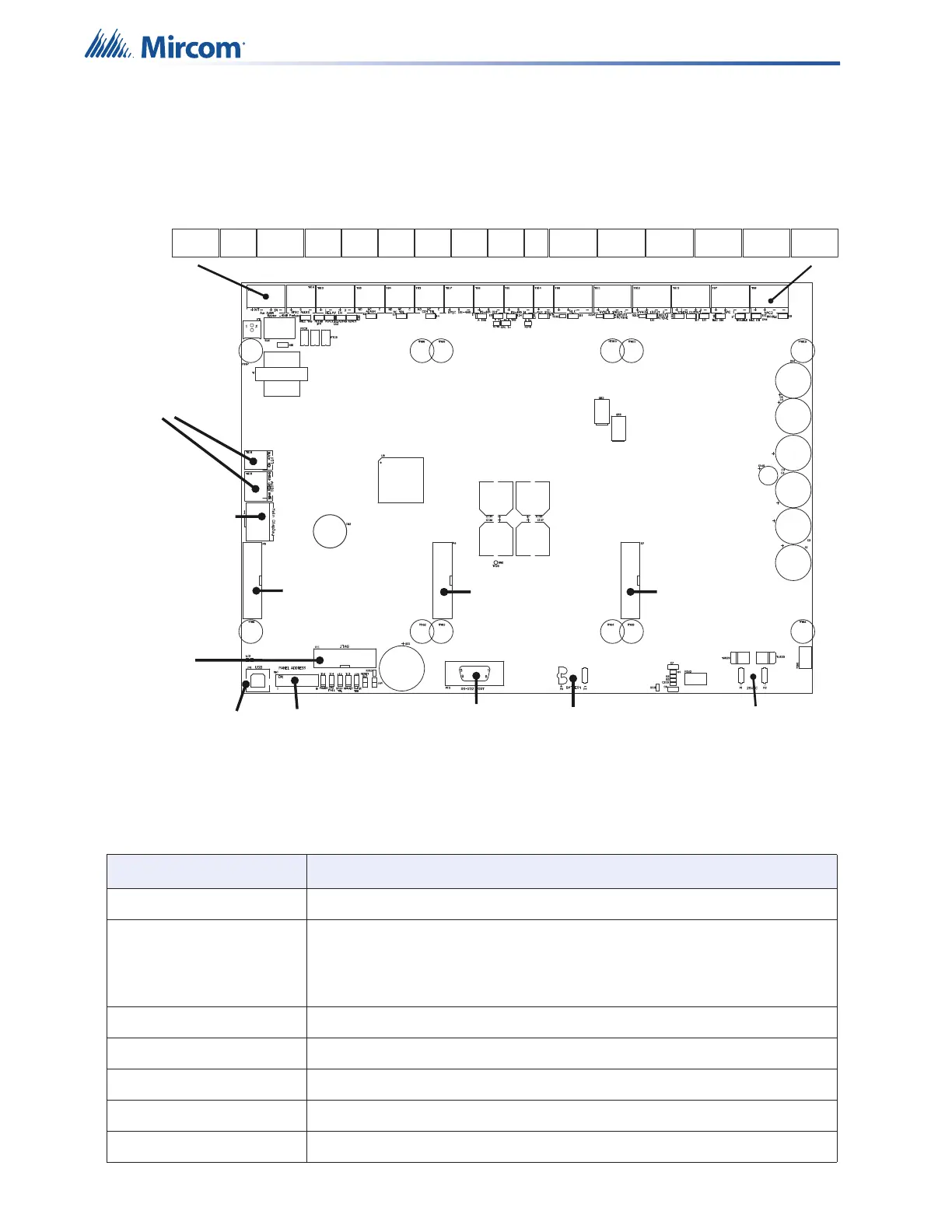
3.3 Main Board Connections
The Main Board is pre-installed on the QX-mini backplate. The Main Board terminals are
shown below. The terminals are depluggable for wiring ease.
Figure 18 QX-mini main board terminals and Jumpers
Table 5 QX-mini Main Board terminals and Jumpers
Terminal/Jumper Description
P1,2 terminals for transformer. No polarity.
P3, P4
terminals for battery
• Red(+) to P3
• Black(-) to P4
P5, P6 terminal for amplifier card QAD-30.
P7 terminal for audio zone splitter QAS-2X8.
P10 Header for RS-232 port. For future use.
P11 Factory Program.
P12 Main display ribbon cable terminal.
SW1
Main Display
Input
Battery
Input
Transformer
Input
+ -
Master
Microphone
Inputs
P6
P5
P7
P10
TS2 TS16
TS10
TS5 TS4 TS3
TS17
TS6
TS1
TS14 TS9
TS11
TS12
TS13
TS7 TS8
AUX
AUDIO
RMIC
AUDIO
RELAY
IN
ALARM
AC
TBL
COM
TBL
RMIC
RS-485
RS-485 RS-485
INOUT
AUX
24V
SLC
SYNCH
SYNCH SYNCH
INPUT 2
INPUT 1
OUTPUT
NAC 1 NAC 2
AUDIO IN
TBL
INOUT 24V
INPUT 1
OUTPUT
+OUT-
+IN-
+ 1 -
+ 2 -
+ 1 -
+ 2 -
+
S
-
+S
-
+S
-
+S
-
NO
NC
C
NO NC
C
NO
NC
C
+
-
+
-
+++
+
+
+
+
++
---
-
-
-
-
--
JP1
P11