47
Installation
TS16 Remote Microphone Audio terminal.
TS10 Relay IN terminal.
TS5 Alarm Relay terminal.
TS4 AC Trouble Relay terminal.
TS3 Common Trouble Relay terminal.
TS17 Remote Microphone RS-485 terminal.
TS6 RS-485 OUT terminal.
TS1 RS-485 IN terminal.
TS2 For future use.
TS14 AUX 24V power terminal.
TS9 SLC terminal.
TS11 SYNCH Input 1 terminal.
TS12 SYNCH Input 2 terminal.
TS13 SYNCH Output terminals S1 and S2.
TS7 NAC 1 terminal.
TS8 NAC 2 terminal.
TS15, TS18 PTT Microphone cable terminal.
JP1 USB port
JW6 Watchdog. (Normally shorted.)
SW1 DIP switch for Panel Address.
SW7 Software reset. (Short to reset.)
JP1 USB connection for configurator, debugging, and firmware updates.
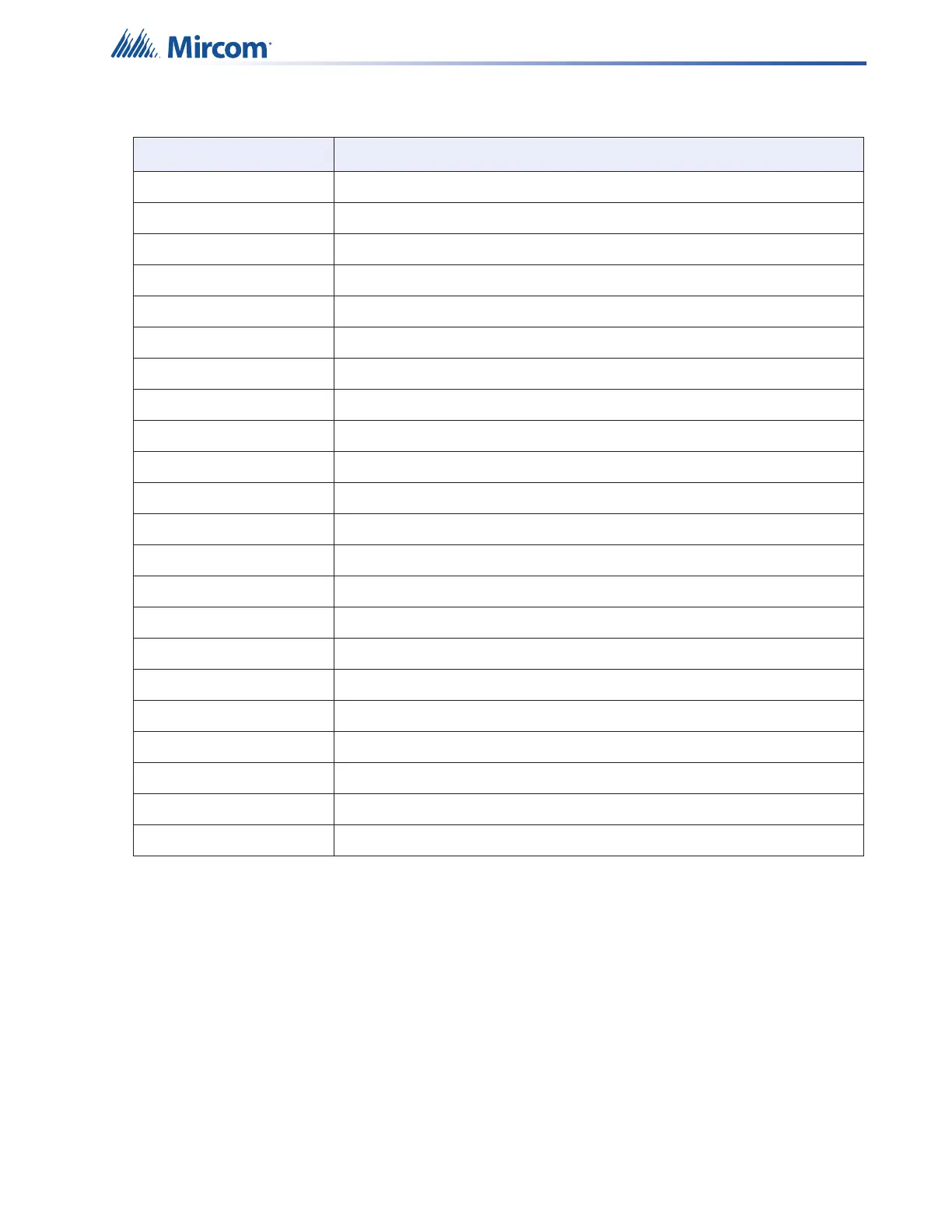
Table 5 QX-mini Main Board terminals and Jumpers (Continued)
Terminal/Jumper Description